
I hesitate to call myself an inventor but one thing I find myself doing often is trying to figure out a simple solution to problems I encounter. One such problem has been with the rear hatch of the Alltrack (also applies to the Mk7 Golf and Sportwagen). First, I coded the hatch to open when the hatch button on the key fob is pressed and then I installed the ECS Tuning hatch pop kit, which is simply a pair of beefier hatch struts and hardware that allow the hatch to lift on its own once the latch is opened (hence the coding).
We go lots of places together as a family and the wagon is usually the family car and there are many times that my wife will run into a store and I will stay in the car with the kids. When she comes out, she will have her hands full with groceries or other things and what I have had to do, rather than get out of the car and open the hatch for her, is remove the key from the ignition, hold it out of the window, and press the hatch button. Kind of annoying but it does get the job done. I know that you can code the car to allow the key fob to be active while the car is running but that wasn't what I wanted. I wanted a physical button like the Mk5s have (even the R32 has it).
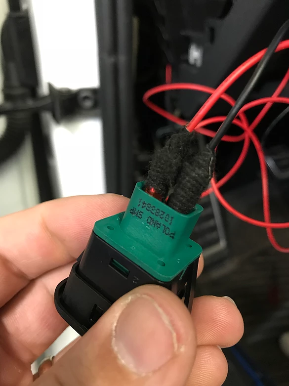
I found a button that I really liked and it is actually from an early 2000s Chevrolet Impala and Monte Carlo. It is available on Amazon and it is an AC Delco made part and if you can find it elsewhere with the pigtail, that would make the wiring a little nicer. I did not know prior to buying it that GM doesn't do connectors like Volkswagen does. If your switch needs a new connector, you have to either buy a brand new harness (in this case, the whole dash harness is over $600) or go to a junk yard and find it.

Let's get to the DIY. As always, you modify your car at your own risk. I am not responsible for your screw ups. Here is the schematic of the switch:

In short, you are tying the factory hatch release wire to the new switch. The switch is non polar so it does not matter which pin is positive or ground. I do not like modifying factory wires so I do my best to make something plug and play to allow for a simple reverse back to stock if needed.
Parts needed:
- Switch
- x1 Female connector: 8W0-972-575
- x1 Male connector: 8W0-971-832
- x1 Female repair wire: 000-979-009-E
- x2 Female terminal pin (alternative): N-907-647-01
- x1 Male repair wire: 000-979-012-E
- x2 Male terminal pin (alternative): 61-13-1-383-672 (BMW)
- x2 Female spade (7/64" or 2.8mm): you can pick these up at almost any auto parts store
- x1 butt connector (22-16 AWG)
- OEM cloth tape: 000-979-950
I like to give the alternative terminal pins because it is way cheaper to buy the pins and bulk wire and make everything to the length you want with the proper crimp tool. In this case, I had one of the male and female repair wires in my stash so I just used that and a heat shrink butt connector.
Tools needed:
- T20 screwdriver (or driver bit in a ratchet)
- small flat head screw driver or trim tool
- terminal removal tool (in this case, a small safety pin or paperclip will also work)
- wire cutter/stripper tool
- crimp tool
I did not take many step by step photos of the entire process because I was working fast and it is pretty simple. If you have any questions, just ask and I will help.
- Step 1: remove the cover at the end of the dash that reveals the fuse panel. Also remove the thin vertical trim that is next to it along the door jamb.
- Step 2: remove the dash cubby underneath the light switch. You do this by opening it and squeezing the outer sides inward.
- Step 3: remove the one T20 screw that is next to the OBDII connector and the plastic cover that it holds.
- Step 4: remove the hood release handle and trim. There are many instructions to this online and the process has not changed since 2006. You will have to first pop the hood and then you can access the handle's retaining clip with a flathead or trim removal tool. You then pull the handle off and remove the small round cover off the head of the trim screw. Then remove the flathead screw. The trim will then come off once you pull up on the door sill trim.
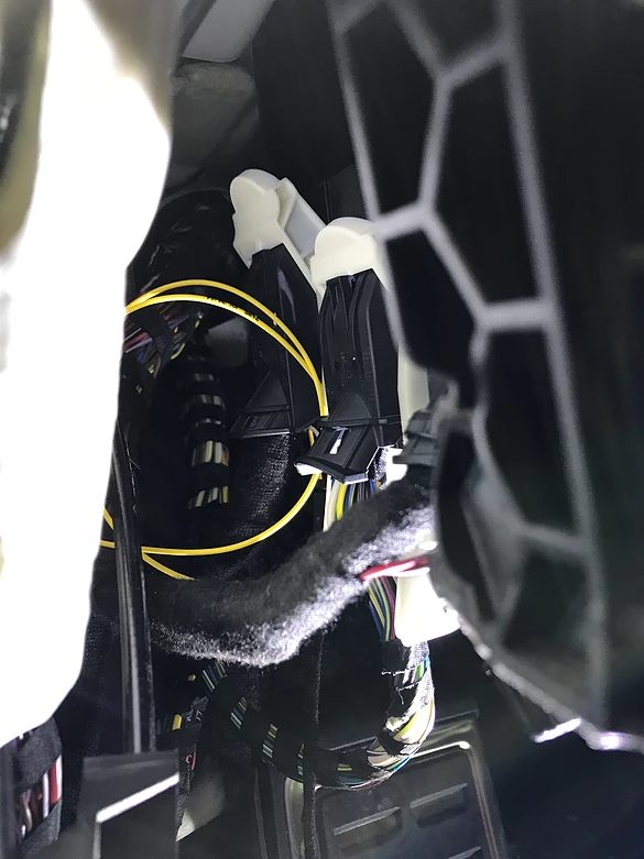
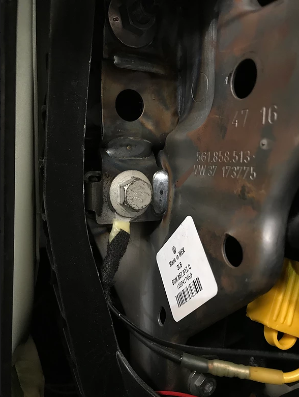
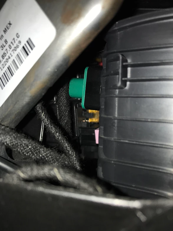
-Step 5: There are three plugs that connect to the BCM (body control module) and they are labeled A, B, and C. They used to be different colors but aren't anymore. For this task, you will need plug A, which will be the closest to the firewall. There is a tab that has to be pushed in before folding the handle down. You may have to unplug the others in order to gain access to this plug or even to be able to pull A all the way out.
- Step 6: Now you will have to remove the main sheath in order to access the individual wires. Carefully snip the small zip tie that is holding the wire loom to the sheath. There are two small tabs that need to be carefully pressed outwards in order for the two smaller connectors to slide out.

Step 7: Both smaller connectors are numbered. You will want to locate pin 32. The connector has number 33 on it, so obviously, 32 is the one next to it. In my case, it was a white wire. You will need to use your terminal pin tool (or safety pin or paper clip) to press the release on the wire and remove the wire. You may need a small pair of needle nose pliers to help pull the wire out, CAREFULLY. Then, insert the female repair wire into pin 32 and make sure it clicks into place. Also make sure the factory wire that you removed is out of the way and easily accessible once the harness is back together.

- Step 8: Insert the two connectors back into the sheath. You don't have to replace the zip tie but you can if you want to. You will now take the factory white wire that you removed from pin 32 and insert it into new male connector (8W0-971-832). It does not matter which position it goes into. Insert the female repair wire into the other position and close the connector. You can plug the entire connector back into the BCM at this point.
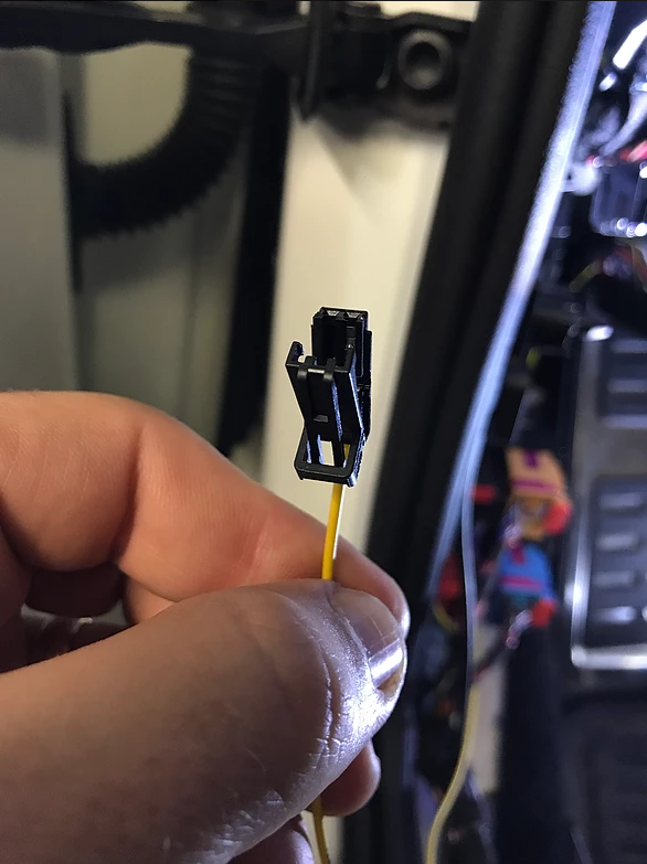
- Step 9: Now you take the new female connector (8W0-972-575) and insert both ends of the male repair wire into it. Snip the repair wire in half and strip the ends and twist together. They are both going to the same position on the switch so I used a butt connector to join them to a single wire.

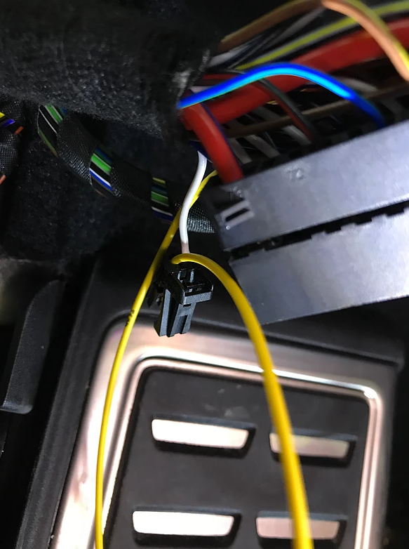
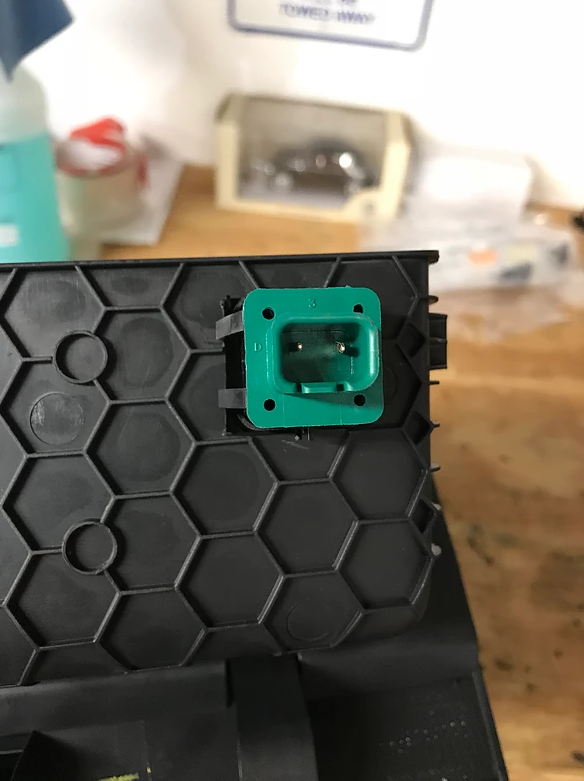
- Step 10: I chose to run the switch inside the dash cubby so not a lot wire is needed but where you choose to put the switch, measure out your wire accordingly. If you are fortunate and have the OEM pigtail to this switch, just connect your wire to either of the leads. I used a 2.8mm female spades to connect to the switch. The other position will be a ground. I removed the 13mm dash bolt in the fuse area and grounded it there.
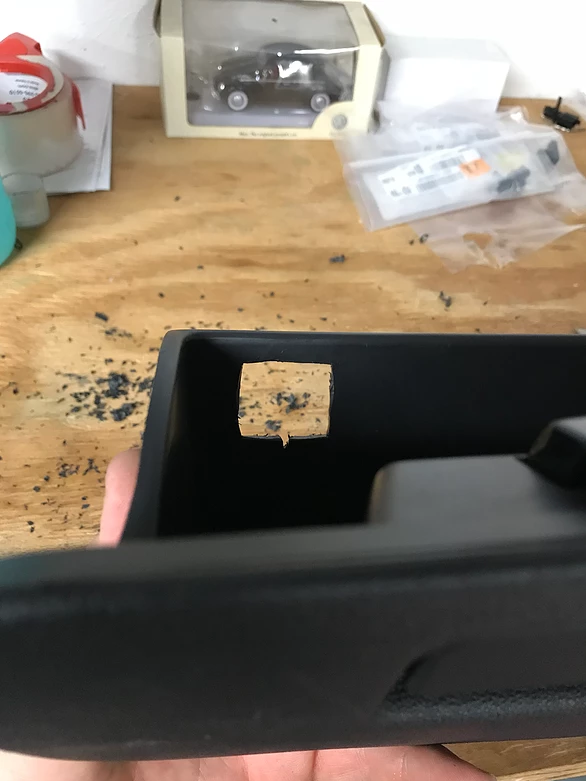
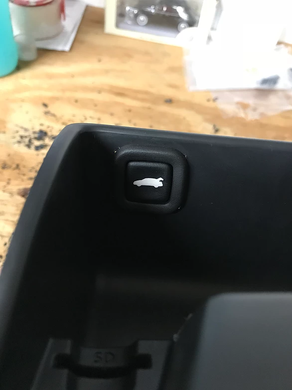
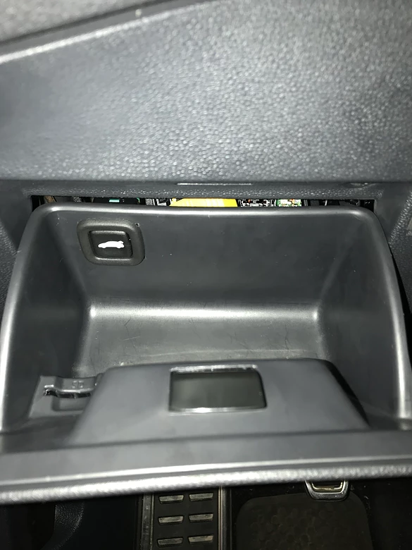
- Step 11: This step is personal preference. I cut out a square in the dash cubby and fit the switch there. There is enough room for the switch when the cubby is closed.

- Step 12: Reassemble everything and coding via VCDS
09-Cent. Elect.
Security Access
31347
Do It!
Adaptation
Channel
12)-Access control-Direkter Auswurf des Heckdeckels
Active
Do It!
And that is it. I can now be lazy and not get out of the car to help my wife.