Mk7 Speedometer Correction

I know I normally publish on Tuesdays and Thursdays but this is fresh in my head so here we go!

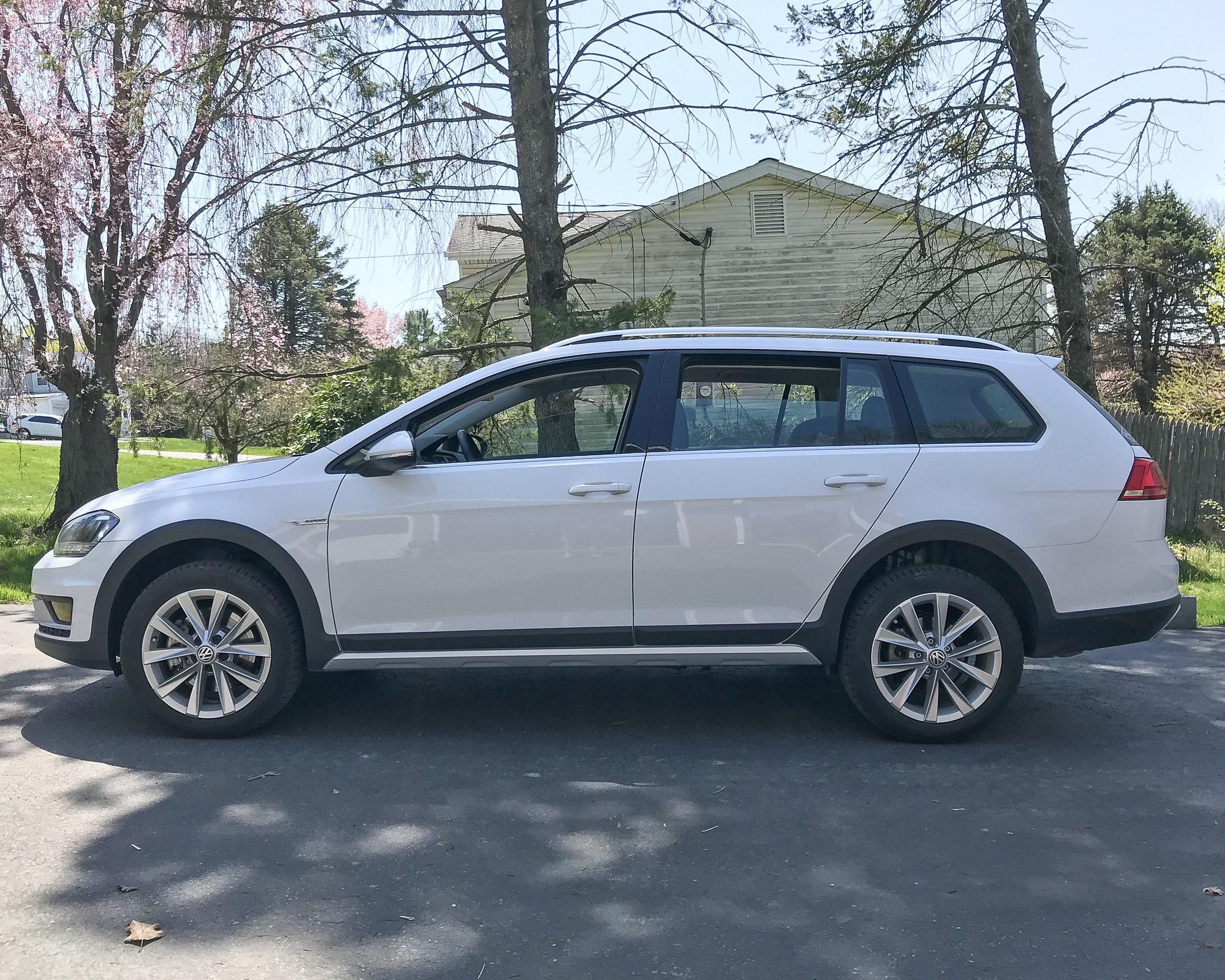
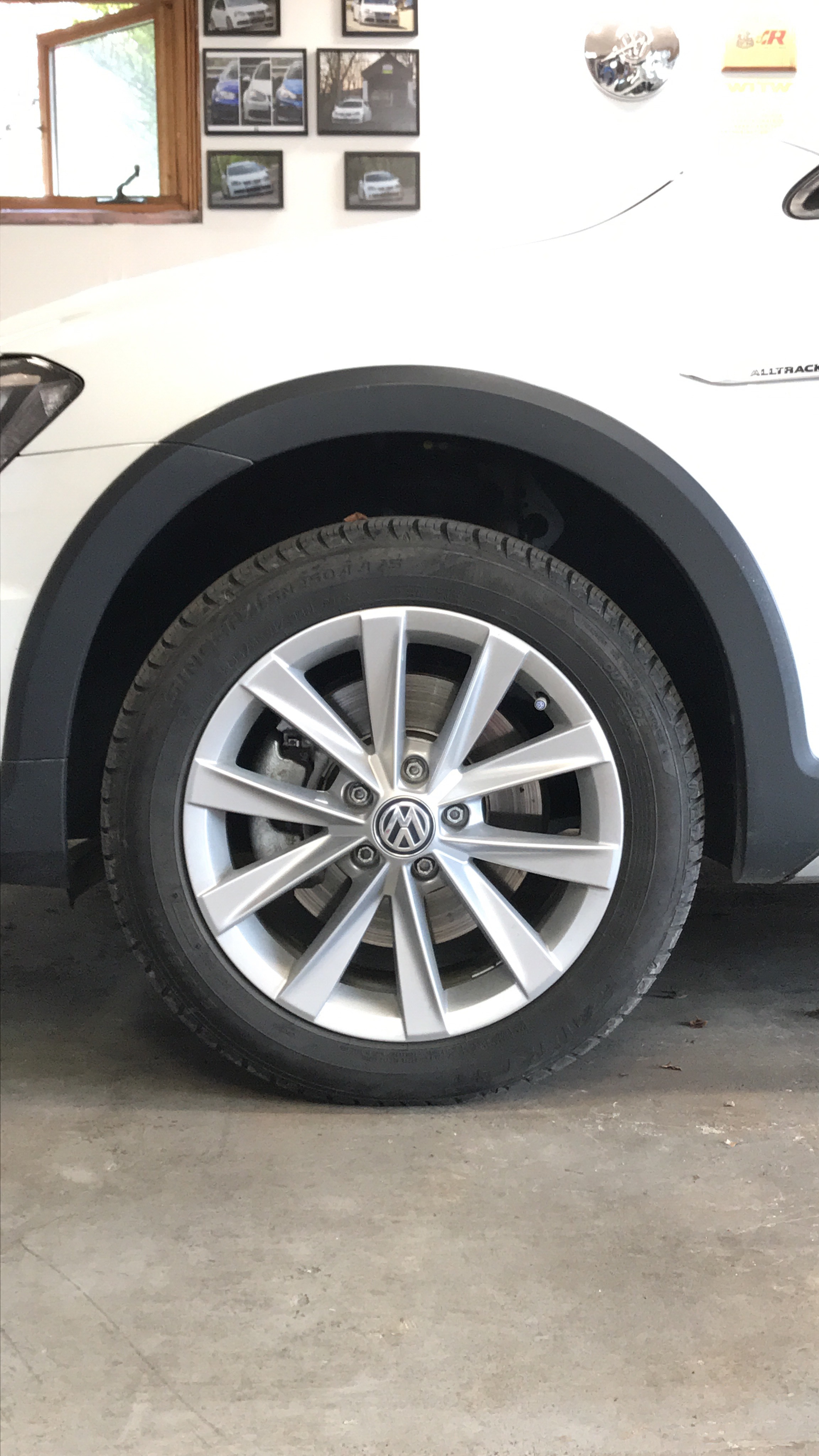
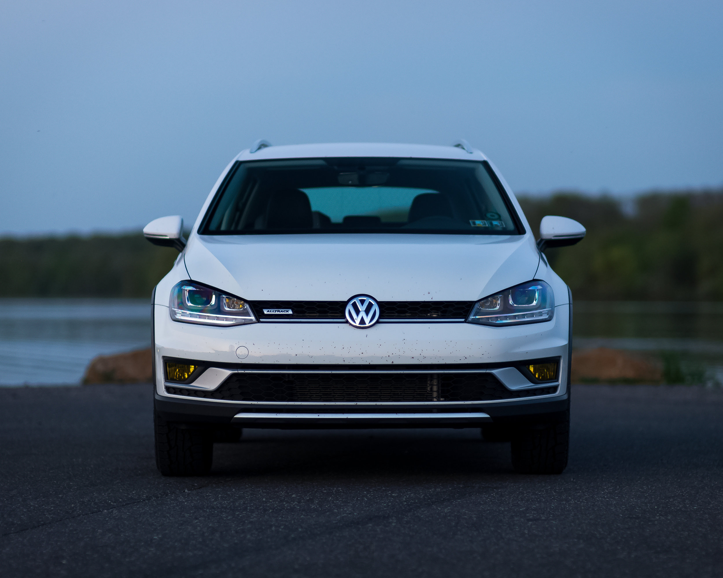
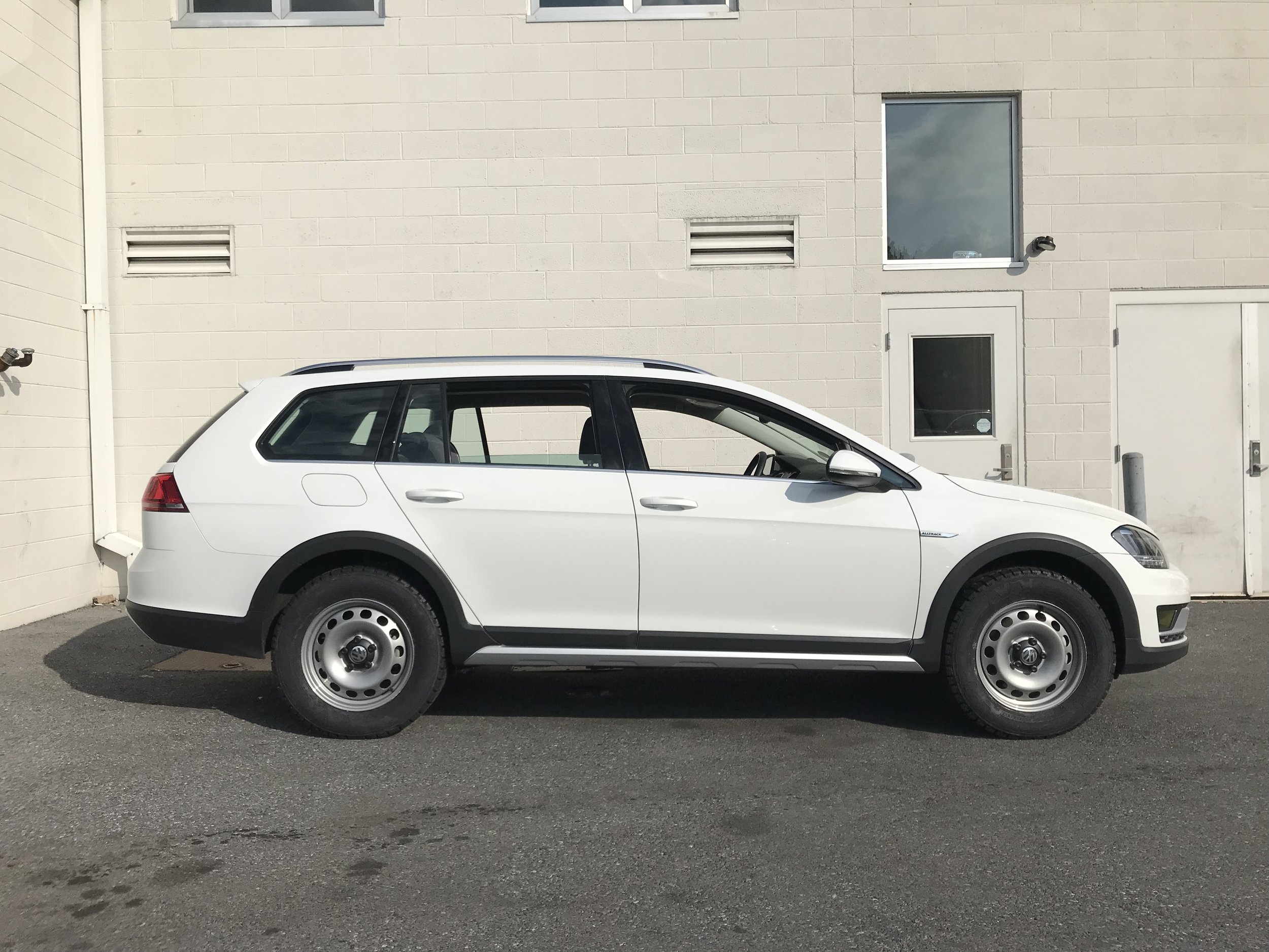
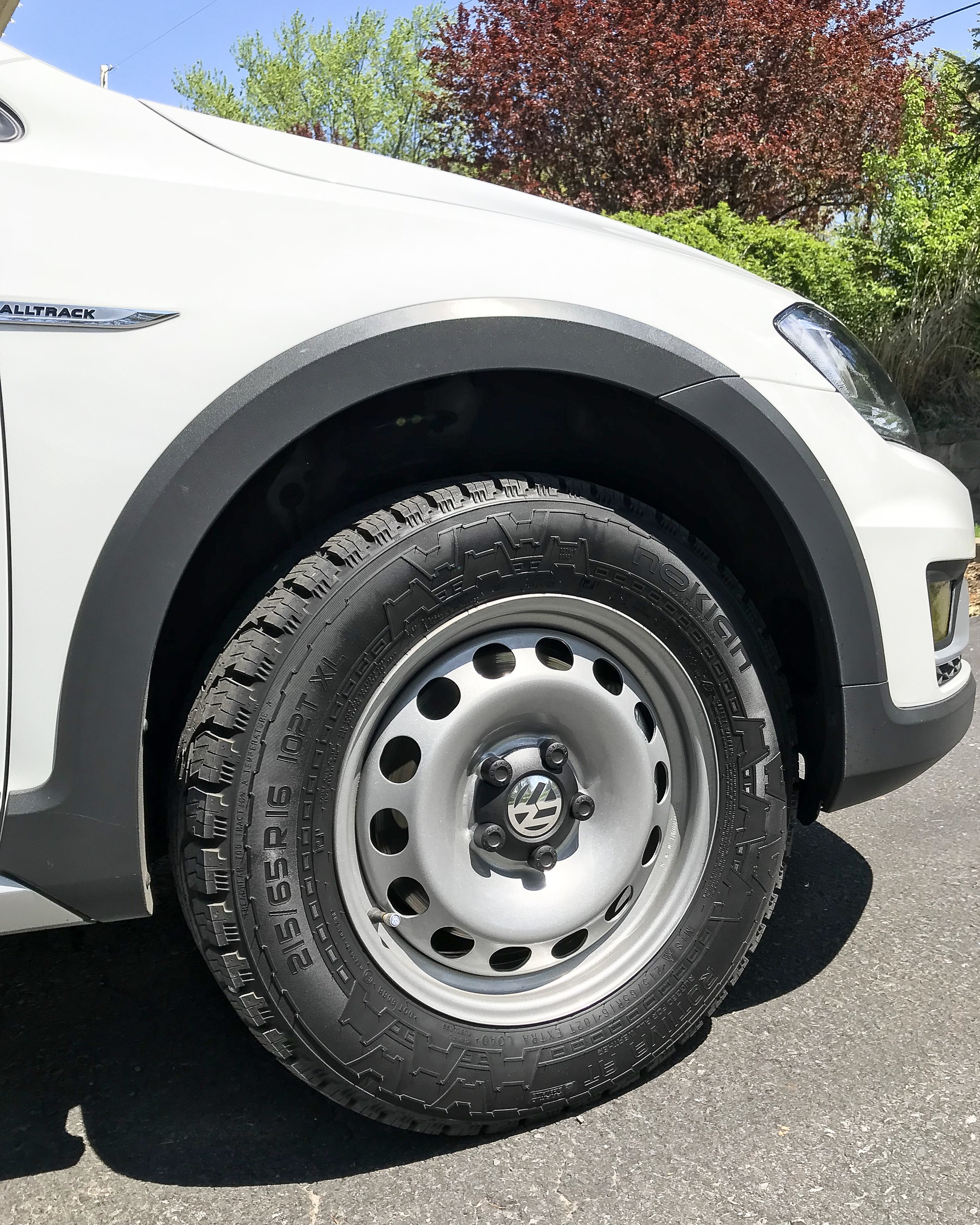
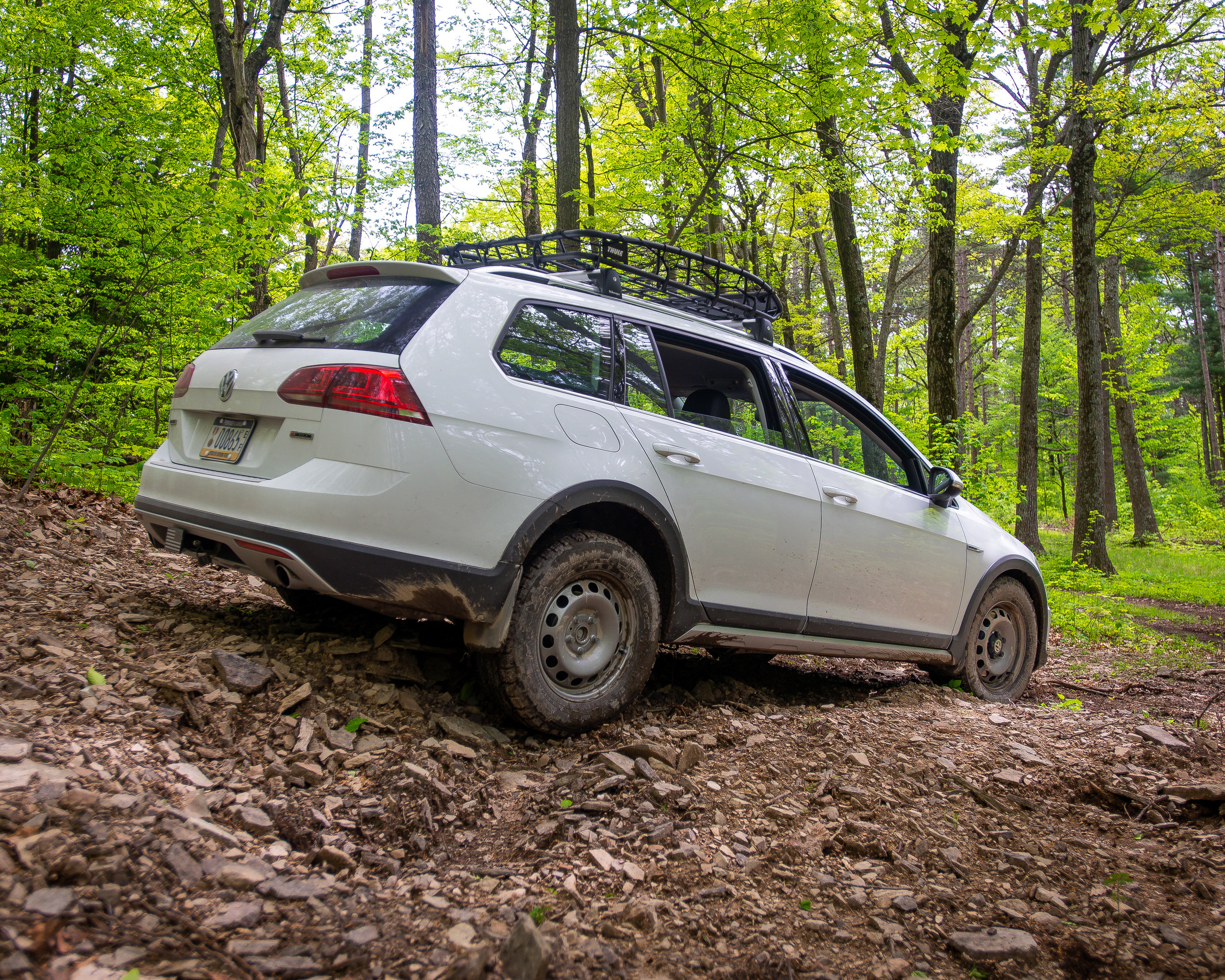
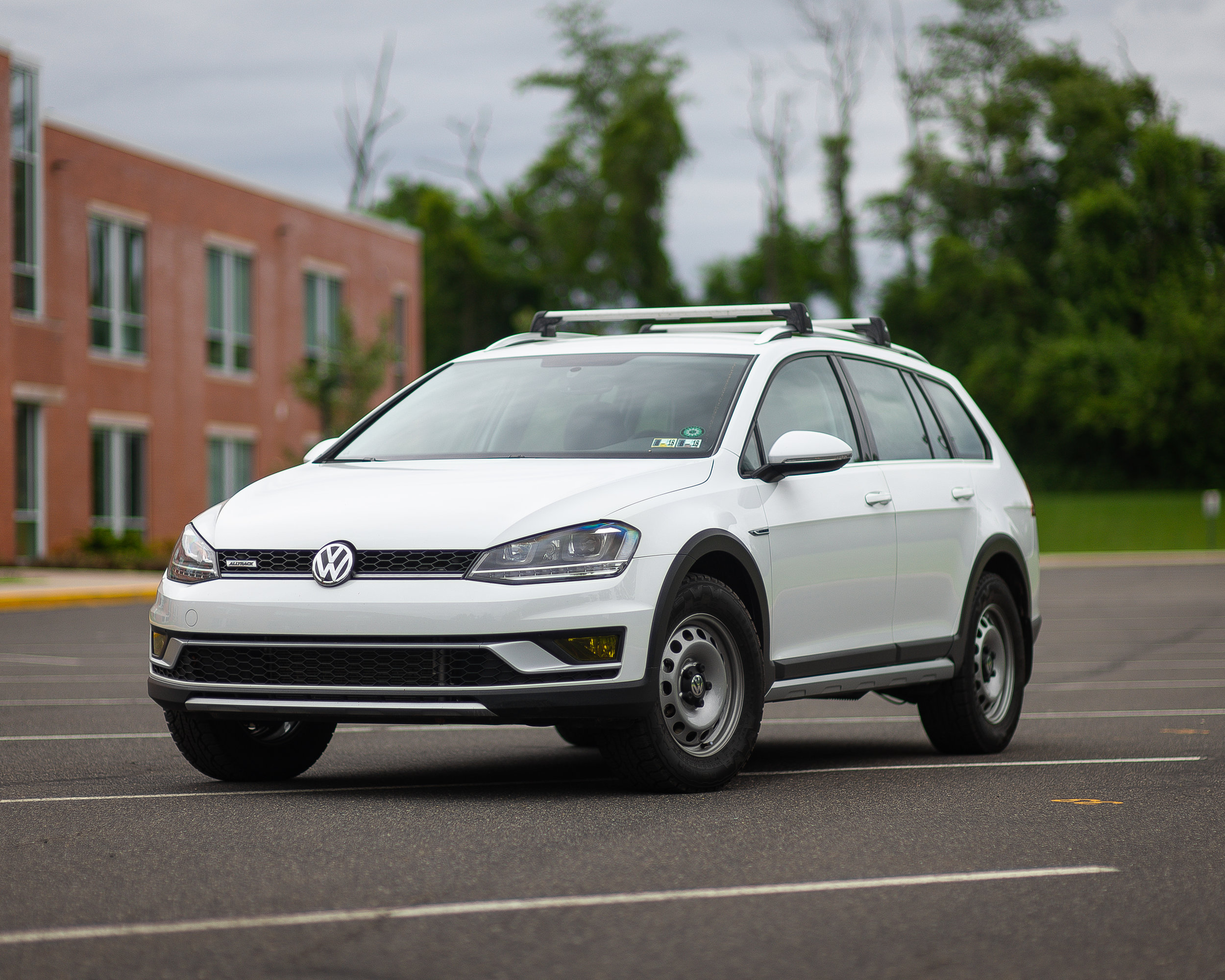
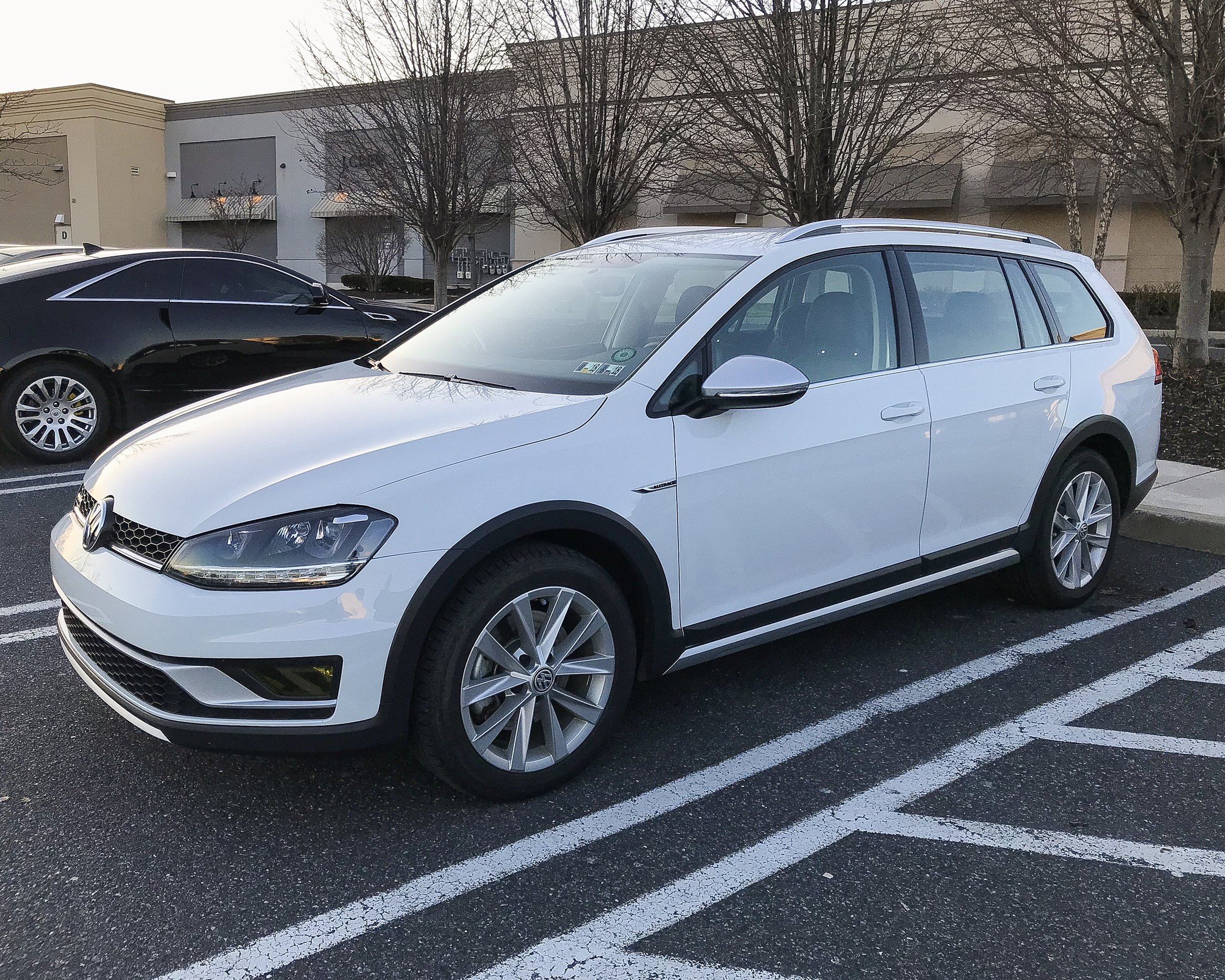
Since putting on the Nokian Rotiivas, my speedometer has been off about 8% from my actual speed due to them being larger than OEM. This may seem like a no brainer to just go slower. True, that is an option but not something I want to calculate while driving. I found some useful information today and put it to the test and was pleasantly surprised with the results. Simply, you have to change the coding of the Instruments and I did this with VCDS. Before I get to the coding, you need to understand the sizing and impulses being read.

When the wheels spin, the ABS sensors measure the rotations and send an impulse to the computer via witchcraft/magic. The computer is programmed to take those impulses and convert them to the speedometer with a set formula that is set with coding.

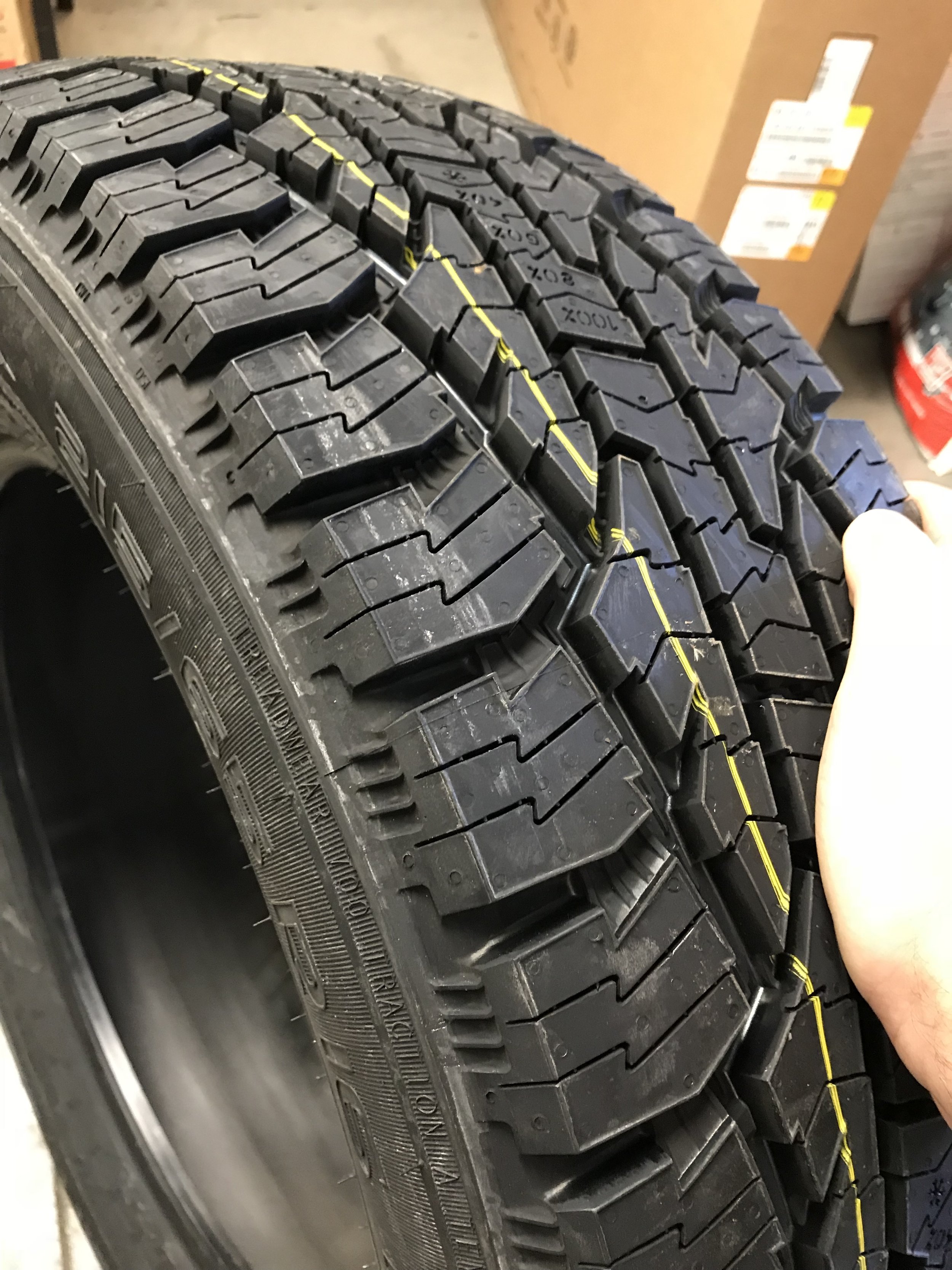
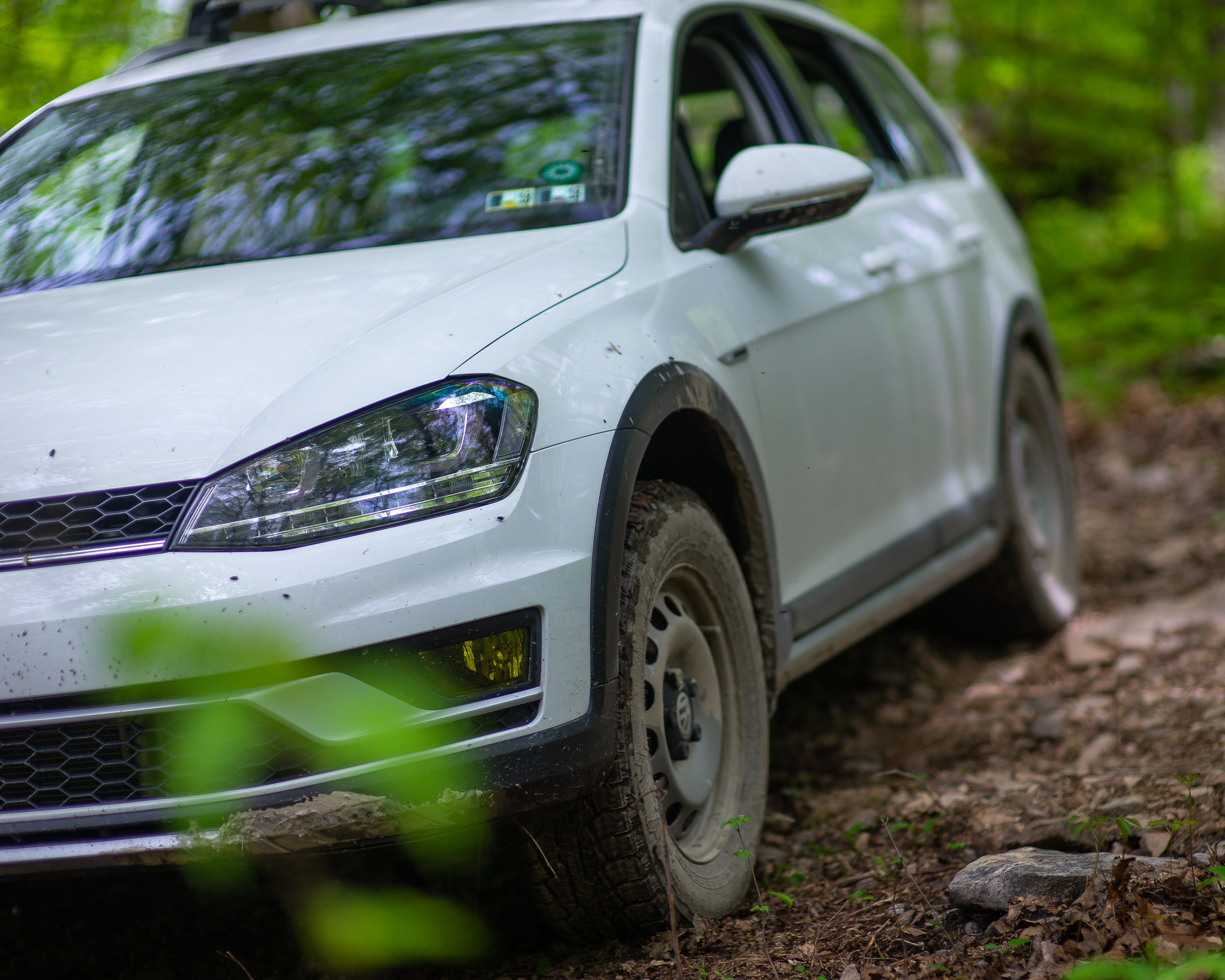
The 215/65R16 tires that I am running break down to this: a diameter of 27" (685.8 mm) and a circumference of 84.84" (2,154.936 mm). There are 43 impulses per revolution and the math I found in order to figure out the revolutions per kilometer, is 1,000,000/circumference (in millimeters). So with this tire, there are 464.05 revolutions per kilometer and 19,954.15 impulses per kilometer. With all of that known, this chart I found was very helpful:

The file was a read only document so I couldn't change the numbers up top but the formulas were there and the important information is on the bottom. Of the numbers shown the one column closest to my numbers were column 4, and when I coded the car to that, my speedometer was where it needed to be. Now to the coding; it is simple.

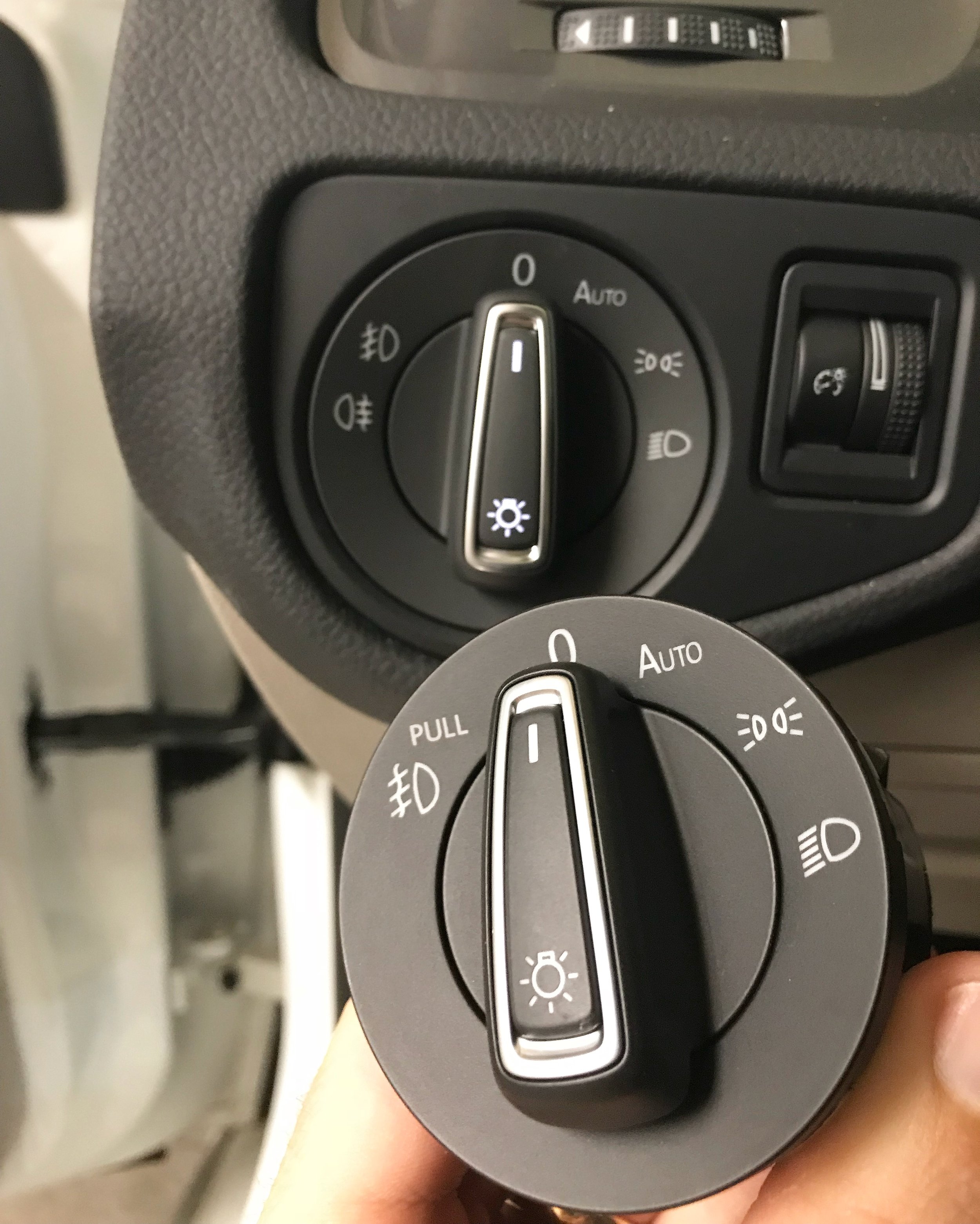
Using VCDS, access the Instruments group 17.

Select Coding and then Long Coding Helper. Once in, toggle over to Byte 3 (the fourth little box with numbers in it). You should see the screen above. The drop down menu from the factory should have 05 Tire Circumference: Variant 6 selected. Click on the drop down menu and select 03 Tire Circumference: Variant 4.

Close the window and select the Do It! button. That's it!

Please, take notice of your stock settings so that if it doesn't work you can revert back. This worked for me and I am really happy to have a normal speedometer/actual speed.

Bearded Elevation System

This post has been a long time coming and I am so happy to be typing this out and I am not even close to being done!

Since buying our Alltrack back in July, I have seen many inquiries about lift kits. Almost every day I was seeing a new post about it. I originally reached out to a company that does lifts for Subarus and I had also done a poll on two different Facebook groups to see what the legitimate interest would be if a kit were to be produced. After the company took a long time to respond, I decided to undertake the task myself. There was a huge learning curve for me since I had not used AutoCAD since high school (almost 15 years ago), nor did I have access to any of the resources needed to 3D print or produce a prototype.

I will fast forward through all of the trial and error bits but I did finally settle on a design that I thought was unique enough that I wanted to protect my intellectual property. I filed for a provisional patent for my front lift kit spacer and before I go further, I guess I should explain why.

The Mk7 Golf is on Volkswagen's MQB platform and like other platforms in the past, it has a MacPherson front strut and a multilink independent rear shock and spring. The concept of lifting a car with this setup is simple: a spacer in between the front strut assembly and the body and the rear spring and the body. The front has a rubber strut mount that is bolted to the body and my concern was, and still is, using a single piece spacer with longer bolts to achieve the lift. This is where my idea for a two piece spacer came into play and that is what I filed a patent for. This will use OEM strength and length bolts and therefore not be more prone to failure from torque.

Recently, I got the lift kit on the car and I first installed a 1/2" lift and then a 1" lift. These will be the two sizes that I will be offering through The Bearded Detailer so I wanted to be sure to install both.

After a week of driving on the kit, I went ahead and ordered the all terrain tires I decided on and dropped off the 16" steel wheels I acquired for powder coating.

I decided on the Nokian Rotiiva AT in a 215/65R16. The reviews were really good and they have a pretty good wear rating. I won't lie to myself or anyone about the amount of highway driving I do and that won't change with this setup so I needed to be able to have a tire that could hold up to that. The steel wheels got finished in a metallic silver very close to the OEM silver alloys and their specs are 16" x 6.5", et50. I also picked up OEM wheel caps (5N0-601-169-X-RW) that I believe reference to a Canadian Tiguan setup. I could be wrong on that but I have had them before and if I am going to run steel wheels, that is the only way for me to go.

Installation day finally came and before the tires were mounted, I coated the wheels with Opti-Coat Pro to make sure they stay as clean as possible when I do end up off road. The dealership was able to balance them with stick on weights since their finish was now similar to alloys. I stuck around and had my friend Connor align the car since the alignment hadn't been touched since the lift kit was installed. I will have more information on the alignment when the kit is finally available to the public but I am content with the specs.

I drove out to get photos that evening and I am so happy with how it all has come together. I will be spacing out the rear wheels 15mm as well. I am content with where the front wheels sit.

Also took the car to a small local show on a whim and the car and kit got some interest. Overall, the car now sits about 1.5" taller than a stock Alltrack and while the tires aren't meant for performance cornering, I am happy with the ride of the car. I do recommend an upgraded rear sway bar and some form of engine tune for a few more ponies due to the added unsprung weight.

Behind The Scenes!


First and foremost: I want to thank everyone that has shared and supported the release of the kit. This can only be a success if more people know about it.


I will get to the alignment. I can't force anyone to get an alignment but do yourself and your tires a favor and get an alignment. You should be doing an alignment once a year at minimum as it is.

 So this is a printout of my alignment and I will state that the BEFORE is not before the lift kit. That is with the lift kit as I drove it to the dealership and the AFTER is how I drove it home and how it currently sits. I never had the car aligned prior to the lift kit but based on printouts of others with stock Alltracks, I can say that the 1" kit added about .4º camber in the front and .13º in the rear. The factory specs call for -.27º ± .50º camber in the front and -1.33º ± .50º camber in the rear.

The front is what should be focused on since it isn't adjustable and the rear is. He was able to get the caster and toe as close to factory as possible and then he adjusted the rear camber about a half a degree to match the front movement. I think my next alignment, I will make the rear match the front closer.

My overall thoughts on the performance of the car? I love it. One thing you have to remember is that the center of gravity has been raised 1" so the will be a slight difference in cornering. This is also true of tires with larger sidewalls. But after a few days of driving, you will get used to the feeling and realize that it is not unsafe. I do about 18,000 miles of driving a year and many family trips with my kids and dog. The last thing I want is an accident with them in the vehicle with me.

Over the Memorial Day weekend, we took a trip up to my parents' house in Bradford County (about 300 miles round trip) and made sure to hit some rural routes that I grew up driving on and leaving the beaten path. The car performed exactly the way I wanted it to.

And that about wraps this up for now. The group buy is still active on Facebook and on the Swag Store until the 21st of June. Again, I thank you all for the support and I look forward to getting these out into the hands of many Alltrack owners!

Mk7 Golf Sportwagen / Alltrack Interior Hatch Button

I hesitate to call myself an inventor but one thing I find myself doing often is trying to figure out a simple solution to problems I encounter. One such problem has been with the rear hatch of the Alltrack (also applies to the Mk7 Golf and Sportwagen). First, I coded the hatch to open when the hatch button on the key fob is pressed and then I installed the ECS Tuning hatch pop kit, which is simply a pair of beefier hatch struts and hardware that allow the hatch to lift on its own once the latch is opened (hence the coding).

We go lots of places together as a family and the wagon is usually the family car and there are many times that my wife will run into a store and I will stay in the car with the kids. When she comes out, she will have her hands full with groceries or other things and what I have had to do, rather than get out of the car and open the hatch for her, is remove the key from the ignition, hold it out of the window, and press the hatch button. Kind of annoying but it does get the job done. I know that you can code the car to allow the key fob to be active while the car is running but that wasn't what I wanted. I wanted a physical button like the Mk5s have (even the R32 has it).

I found a button that I really liked and it is actually from an early 2000s Chevrolet Impala and Monte Carlo. It is available on Amazon and it is an AC Delco made part and if you can find it elsewhere with the pigtail, that would make the wiring a little nicer. I did not know prior to buying it that GM doesn't do connectors like Volkswagen does. If your switch needs a new connector, you have to either buy a brand new harness (in this case, the whole dash harness is over $600) or go to a junk yard and find it.

Let's get to the DIY. As always, you modify your car at your own risk. I am not responsible for your screw ups. Here is the schematic of the switch: 

In short, you are tying the factory hatch release wire to the new switch. The switch is non polar so it does not matter which pin is positive or ground. I do not like modifying factory wires so I do my best to make something plug and play to allow for a simple reverse back to stock if needed.

 Parts needed:

 - Switch 

- x1 Female connector: 8W0-972-575

- x1 Male connector: 8W0-971-832

- x1 Female repair wire: 000-979-009-E

- x2 Female terminal pin (alternative): N-907-647-01

- x1 Male repair wire: 000-979-012-E

- x2 Male terminal pin (alternative): 61-13-1-383-672 (BMW)

- x2 Female spade (7/64" or 2.8mm): you can pick these up at almost any auto parts store

- x1 butt connector (22-16 AWG)

- OEM cloth tape: 000-979-950

I like to give the alternative terminal pins because it is way cheaper to buy the pins and bulk wire and make everything to the length you want with the proper crimp tool. In this case, I had one of the male and female repair wires in my stash so I just used that and a heat shrink butt connector.

Tools needed:

- T20 screwdriver (or driver bit in a ratchet)

- small flat head screw driver or trim tool

- terminal removal tool (in this case, a small safety pin or paperclip will also work)

- wire cutter/stripper tool

- crimp tool

I did not take many step by step photos of the entire process because I was working fast and it is pretty simple. If you have any questions, just ask and I will help.

- Step 1: remove the cover at the end of the dash that reveals the fuse panel. Also remove the thin vertical trim that is next to it along the door jamb.

- Step 2: remove the dash cubby underneath the light switch. You do this by opening it and squeezing the outer sides inward.

- Step 3: remove the one T20 screw that is next to the OBDII connector and the plastic cover that it holds.

- Step 4: remove the hood release handle and trim. There are many instructions to this online and the process has not changed since 2006. You will have to first pop the hood and then you can access the handle's retaining clip with a flathead or trim removal tool. You then pull the handle off and remove the small round cover off the head of the trim screw. Then remove the flathead screw. The trim will then come off once you pull up on the door sill trim.

-Step 5: There are three plugs that connect to the BCM (body control module) and they are labeled A, B, and C. They used to be different colors but aren't anymore. For this task, you will need plug A, which will be the closest to the firewall. There is a tab that has to be pushed in before folding the handle down. You may have to unplug the others in order to gain access to this plug or even to be able to pull A all the way out.

- Step 6: Now you will have to remove the main sheath in order to access the individual wires. Carefully snip the small zip tie that is holding the wire loom to the sheath. There are two small tabs that need to be carefully pressed outwards in order for the two smaller connectors to slide out.

Step 7: Both smaller connectors are numbered. You will want to locate pin 32. The connector has number 33 on it, so obviously, 32 is the one next to it. In my case, it was a white wire. You will need to use your terminal pin tool (or safety pin or paper clip) to press the release on the wire and remove the wire. You may need a small pair of needle nose pliers to help pull the wire out, CAREFULLY. Then, insert the female repair wire into pin 32 and make sure it clicks into place. Also make sure the factory wire that you removed is out of the way and easily accessible once the harness is back together.

- Step 8: Insert the two connectors back into the sheath. You don't have to replace the zip tie but you can if you want to. You will now take the factory white wire that you removed from pin 32 and insert it into new male connector (8W0-971-832). It does not matter which position it goes into. Insert the female repair wire into the other position and close the connector. You can plug the entire connector back into the BCM at this point.

- Step 9: Now you take the new female connector (8W0-972-575) and insert both ends of the male repair wire into it. Snip the repair wire in half and strip the ends and twist together. They are both going to the same position on the switch so I used a butt connector to join them to a single wire.

- Step 10: I chose to run the switch inside the dash cubby so not a lot wire is needed but where you choose to put the switch, measure out your wire accordingly. If you are fortunate and have the OEM pigtail to this switch, just connect your wire to either of the leads. I used a 2.8mm female spades to connect to the switch. The other position will be a ground. I removed the 13mm dash bolt in the fuse area and grounded it there.

- Step 11: This step is personal preference. I cut out a square in the dash cubby and fit the switch there. There is enough room for the switch when the cubby is closed.

- Step 12: Reassemble everything and coding via VCDS

  • 09-Cent. Elect.

  • Security Access

    • 31347

    • Do It!

  • Adaptation

    • Channel

      • 12)-Access control-Direkter Auswurf des Heckdeckels

      • Active

      • Do It!

And that is it. I can now be lazy and not get out of the car to help my wife.

Volkswagen Alltrack - Coating

The time finally came for me to coat my own Alltrack with Opti-Coat Pro+! I waited way too long to do this but thankfully, due to proper maintenance and using Optimum No Rinse and Opti-Coat Hyper Seal, there were not many defects to correct at all! Optimum Primer Polish made quick work and before I knew it, the car looked the best that it has ever looked in the seven months I have had it! This is the newest formula of Pro+ and it is still a lifetime coating with a seven year warranty, backed by Optimum Polymer Technologies.

Volkswagen Alltrack

Jeff approached me not long ago about wanting to add rear fogs to his Alltrack and since I had already done this to my Alltrack, this was an easy task. He also wanted to add the European halogen tail lamps to his car, which adds an amber turn signal to the car instead of a red one. The entire kit also included a light switch to allow for the rear fog, coding, and LED reverse and fog bulbs. Thanks Jeff, enjoy!

If you are interested in the bulbs and harness used: Rear fog | Reverse | Rear fog harness