Mk5 Golf R32 Silicone Coolant Hoses Info and Review

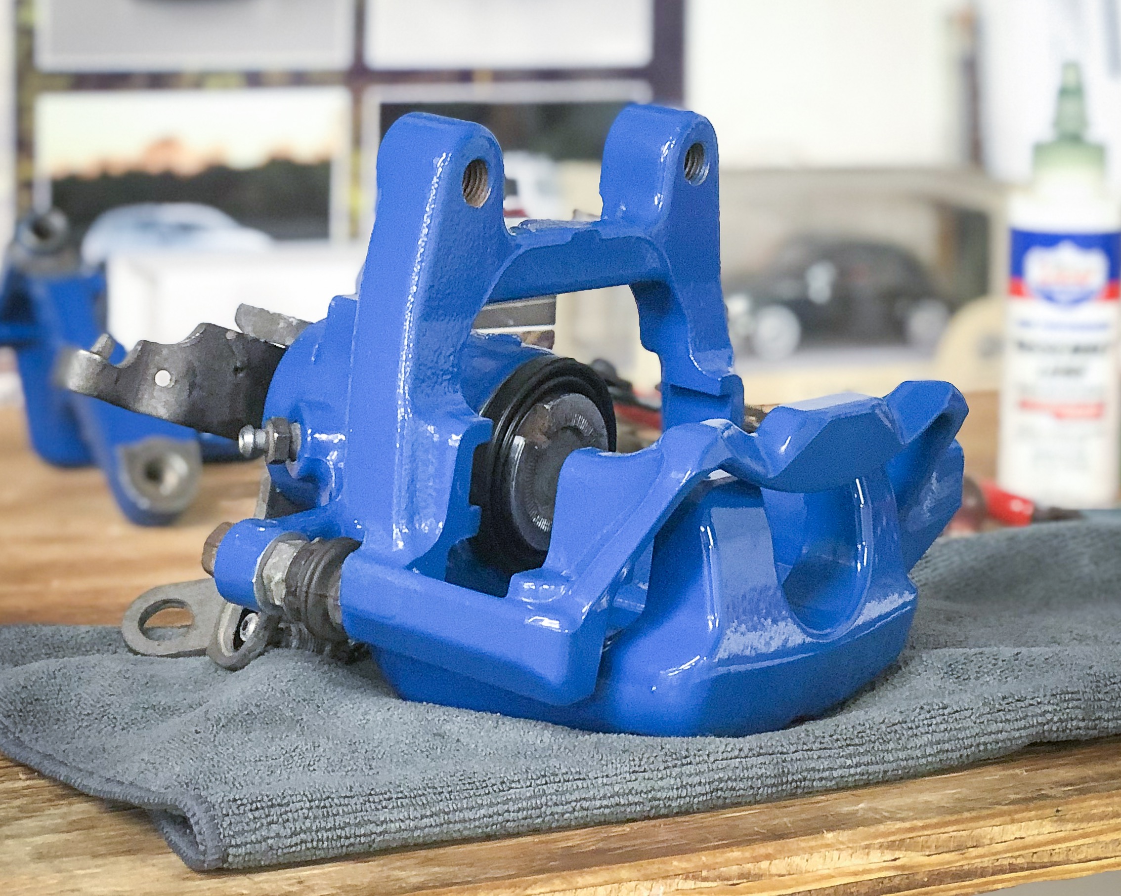
Wile doing a recent oil change, I discovered that the original rubber coolant hoses had started to bubble. This meant that the car was getting parked until I could replace the hoses because I knew they were ticking time bombs. These bubbles were more than likely caused by oil within the coolant lines, which I know was caused by a failed DSG cooler last year. Even though I did a very thorough flush, the damage had already been done and not all of the oil was evacuated.

Once I looked up the prices for the OEM replacement hoses, it was an easy decision to purchase silicone hoses. The OEM hoses were well over $500 at my wholesale cost…hell no. Now, for silicone, there are two companies that offer a kit for the Mk5 R32: Forge Motorsport and Addiction Motorsport. Both companies are located in the UK (Forge has a US location) and both offer the kits in three different colors. However, Forge’s kit is meant specifically for a manual transmission R32 (Europe only option) but AM’s kit is for a DSG R32. Seems like a simple solution, right?

Wrong. Addiction Motorsport was out of stock of their black kit, which is the color I wanted, and through speaking with them via email (very quickly I will add), I was told that it would end up being about 3-4 weeks before they had it back in stock. With Wookies in the Woods fast approaching (4 weeks from when I contacted them), they were no longer an option for me, which is unfortunate because I really do like the look of their kit and the fact that is meant for a DSG car. Instead, I ordered a black Forge kit, knowing that it came with no instructions, additional data, and that modification would be necessary to work with a DSG car.

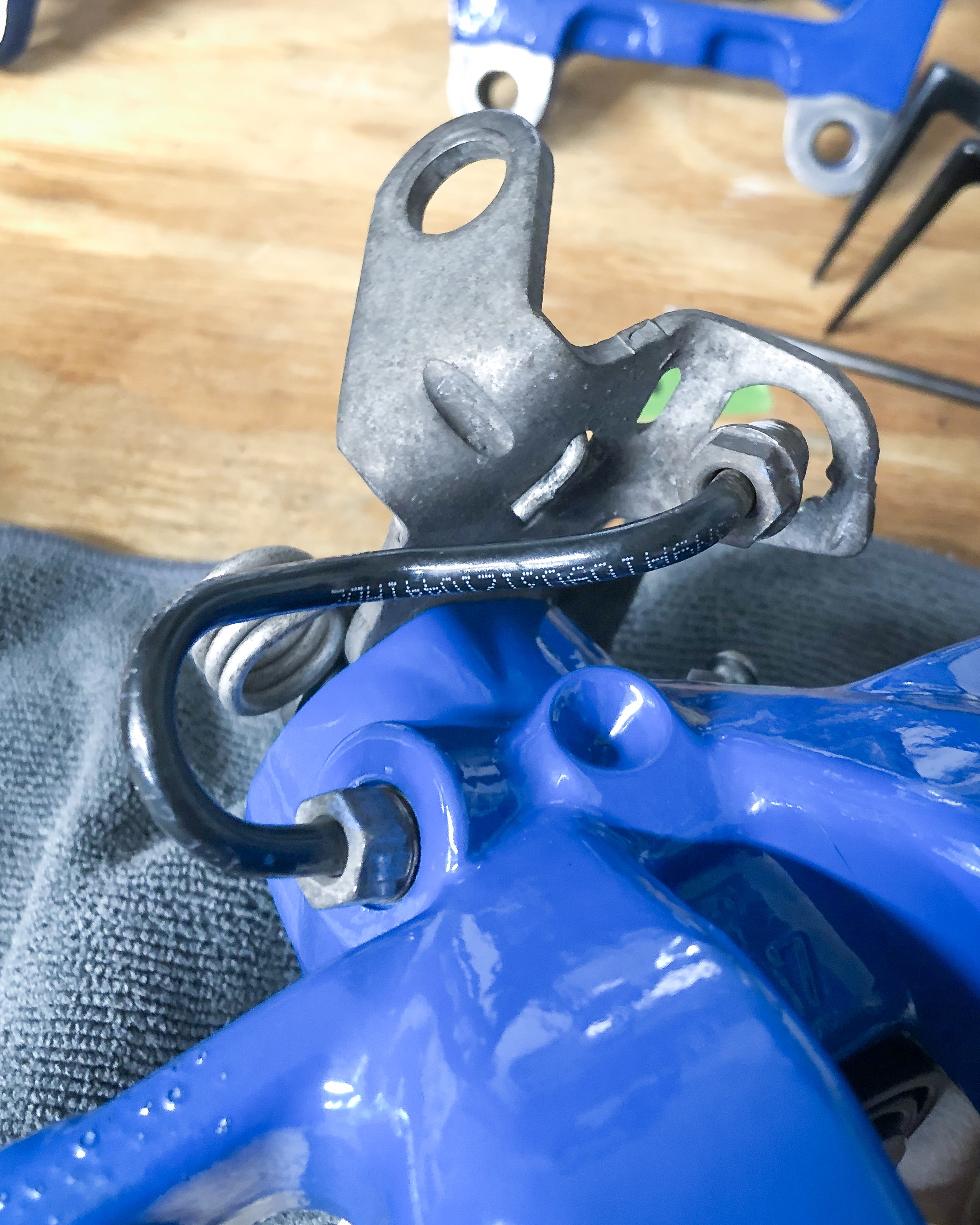
The kit showed up quickly and did include nice hose clamps. I had called Forge Motorsport US when I ordered them to see if they knew what else was needed in addition to the kit and was flat out told no and that they don’t know. I mocked up all the hoses to start figuring this out since there aren’t any documented DIY or informational posts that I could find. This leads us to what you are reading now. Because Forge doesn’t tell you what is what, I am here to help you save time.

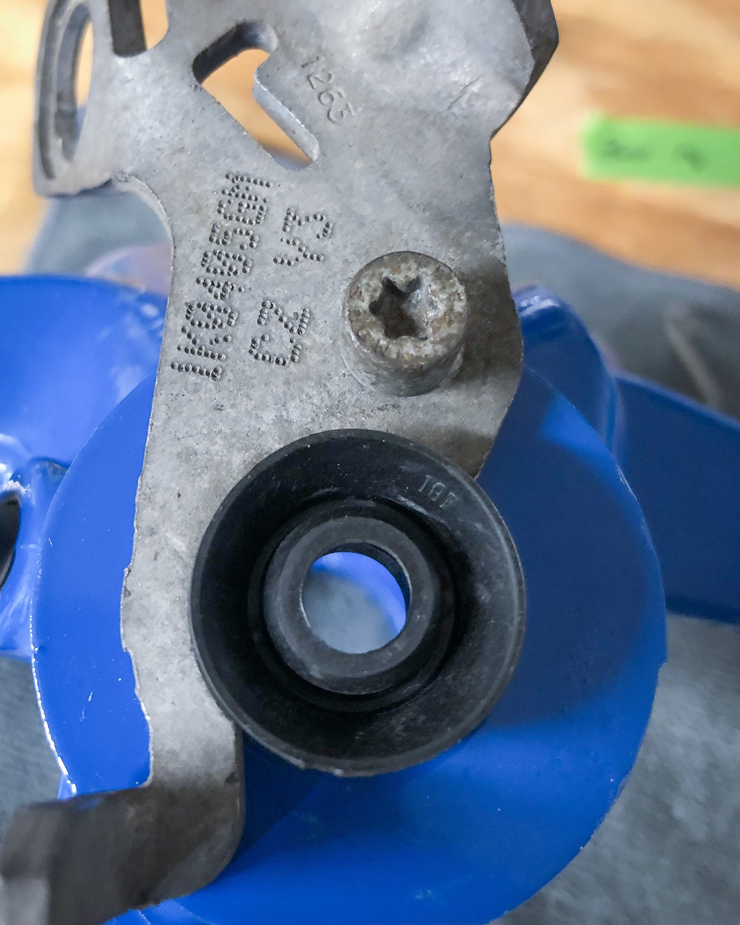
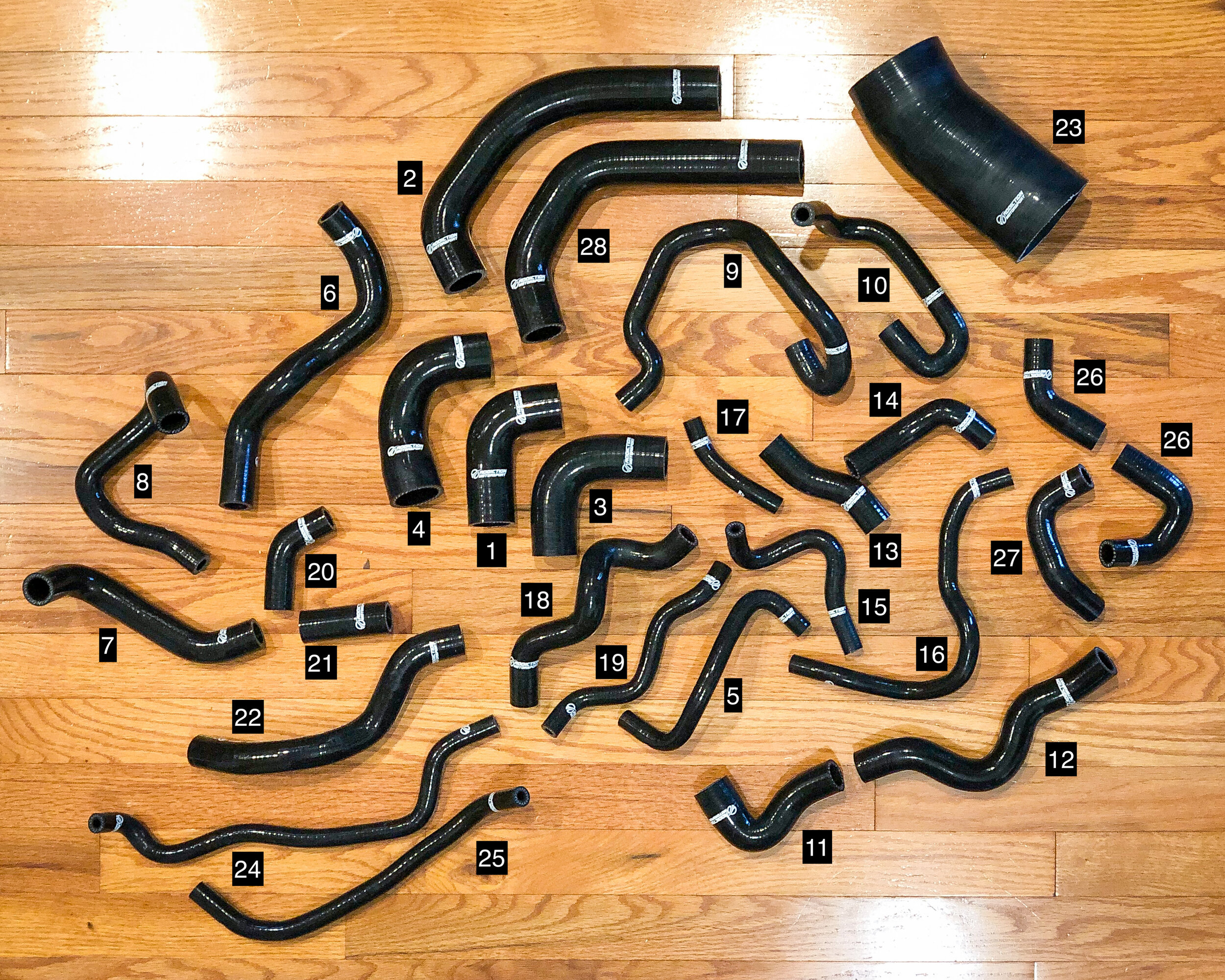
Each hose has a three digit stamp on it (I really hope they all do and that they are all the same) and I made a spreadsheet showing each hose and it’s corresponding OEM part number, location, and which hoses are missing from the kit.


Now, I am not going to do a full actual DIY because, well, it is a lot and not a small task. What I will say is that you will need to put the radiator support into the service position at a minimum in order to get two hoses (one from the oil cooler to the block and one from the aux water pump to the block). In addition, you will need remove the thermostat housing and water pipe (aka the crack pipe) in order to get to those same hoses. Everything else can be accessed with just the intake out of the way. You will notice that there are four lines that say “needs to be cut” and it is not that intimidating so long as you have a sharp knife. You simply need to lay the hose next to it’s corresponding OEM hose and mark where the breaks need to happen. Also, don’t forget to transfer any heat shield, bumper, or sleeves from the OEM hoses to the new hoses: they’re there for a reason.

I will also mention that the longer oil cooler hose (goes to the block) is not the same shape as the OEM hose but can work, once the larger end is trimmed. I would have to look up why this is…possibly the manual R32 has a different cooler if I had to guess. I was also told by three people that they were able to modify one of the Forge hoses to work with the DSG cooler but no matter what configuration I tried, I could not figure this out. This is why I have the OEM hoses for that listed, as well as a new heater hose (really weird that it wasn’t replaced with the Forge kit), and one smaller hose on the lower radiator line that connects the DSG cooler to the system.

For me, since everything was open and there was still residual oil in the system, a full flush using Volkswagen’s Clean Sol (G-052-188-A3) will be done. I used this last year and I will say that it does a really good job. It is tedious to do a full flush but I don’t want to do any of this again for a long time.

Time to talk turkey: the Forge kit costs $400 (sales, free shipping, and hose clamps are available depending on where you order from) and the four missing hoses will cost $145.27 MSRP from a dealer. The Addiction Motorsport kit is listed on their site 315.99 £ ($458.44) but that does include their VAT for UK buyers. In talking with them via email, they will remove the VAT for US buyers with proof of residence. This makes their kit 263 £ ($381.56) plus shipping (25 £ or $36.27) and this means (in theory) you will not need to buy the extra OEM hoses, although I cannot verify this because I do not have their kit in front of me. Perhaps I will buy their kit just for a comparison, though I will not install after I have already gone through all this trouble.

If time wasn’t an issue, I would have waited for the black Addiction Motorsport kit to get back in stock (yes, even if the prices were identical). I also do not know if they provide clamps and any further information or instructions with their kit but I think it is worth the savings in price and hassle of having to modify. I hope this helps and if you need any more information, don’t hesitate to ask.


UPDATE!

Once the Addiction Motorsport hoses in black were available, I did order them, for science. Man, I really wish these would have been available when I was doing the job but now I know for the future and so will all of you.

I see no physical issues with the kit and they also come with no instructions or information as to what is what. One major downside to this kit is there are no identifying marks like the Forge kit so there is no way for me to list what is what like I did with them. What I can do is get as close as I can to comparing them:

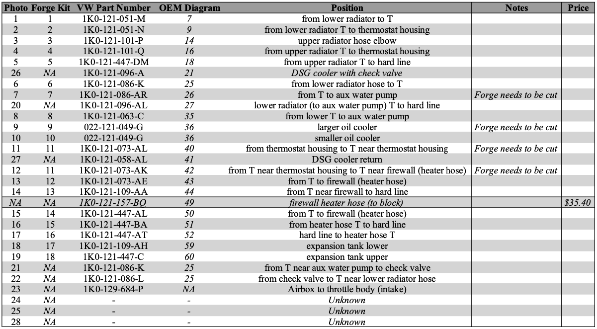
As you can see from the chart, I am clueless as to the locations of three hoses (24, 25, and 28) and honestly, I am not taking my car apart to figure that out. If you purchase this kit and figure it out, please let me know. I also could be wrong but I do not see a hose to replace one of the two heater core hoses, which the Forge kit also does not provide.

I hope this helps and I do have the hoses listed for sale (click HERE for the listing) for someone that needs the kit in the States. I am losing a little money in the name of documenting as much as possible for the Mk5 R32 coolant hose replacements.

Mk7 Golf Sportwagen / Alltrack Towing Guide

Since owning my first 2017 Alltrack, I have seen a new towing capacity or general towing post weekly, sometimes almost daily, so I decided to put everything towing related in one post to make it easier to find.

No towing at all is RECOMMENDED for any Golf Variant (Sportwagen and Alltrack) in the United States (I imagine Canada might be similar since that falls under the North American Region). That is the official stance from Volkswagen. One common rumor that gets passed around is that if you tow, you will void your warranty. Your warranty won’t be voided if you tow, however, if you tow and let’s say your clutch goes bad because you decided to tow 3 tons of bricks, then it’s likely that repair will not be covered by your warranty.

Now, we all know that the same vehicles exist in the United Kingdom and Europe and over there they are rated for towing. It is important to note that since towing is common place over there, the vehicles are able to be equipped with an OEM trailer module which allows for improved stability and cooling when towing. Also, most tow with trailer brakes. Here is a breakdown of what their ratings are:

  • 1.8T Sportwagen: 1,500 kg / 3,307 lbs braked (750 kg / 1,653 lbs un-braked)

  • 1.4T Sportwagen: 1,500 kg / 3,307 lbs braked (670 kg / 1,477 lbs un-braked)

  • 2.0 TDI Sportwagen: 1,600 kg / 3,527 lbs braked (710 kg / 1,565 lbs un-braked)

  • 1.8T Alltrack: 1,500 kg / 3,307 lbs braked (750 kg / 1,653 lbs un-braked)

  • 2.0 TDI Alltrack: 2,000 kg / 4,409 lbs braked (750 kg / 1,653 lbs un-braked)

It is important to remember that these numbers are for braked trailers and the hitches are not 1.25” hitches. Also these numbers are the same for manual and automatic (DSG) transmissions. Since most people I know that tow with their Golf Variants don’t have trailer brakes (myself included), here is a very safe rule of thumb: regardless if you use a 2” or a 1.25” hitch, do not exceed 91 kg / 200 lbs tongue weight and do not exceed 907 kg / 2,000 lbs total weight. That is the rating of Class 1 hitches (that is what is mostly available for our cars). Let’s move on to options for hitches.

  • Curt: 114223 Class 1, 1.25” - this part number includes the receiver and ball mount

  • Curt: 11422 Class 1, 1.25” - this part number is just the receiver, no ball mount

  • Draw-Tite: 24949 Class 1, 1.25”

  • EcoHitch: XV1VWGOLF02 Class 1 Hidden, 1.25” or 2”

  • Westfalia: 321782, 50mm ball and rated for 80 kg / 176 lb tongue and 2,000 kg / 4,409 lb towing

As for trailer wiring, there are two manufacturers with piggy-back options that I know of, and all work specifically on the NAR (North American Region) lighting behaviors of the brake and turn signals operating at the same time.

  • 2015-2017 with halogen tail lamps: Curt C56391

  • 2015-2017 with halogen tail lamps: Tekonsha 118730

  • 2018+ with LED tail lamps: Curt C59236 - doesn’t appear to have plug and play adapter

  • 2018+ with LED tail lamps: Tekonsha 118730

  • If you have European tail lamps or coded your NAR tail lamps to function as European, you’ll need to splice in Curt 56496 in order to have full trailer functions.

  • If you are interested in retrofitting an OEM trailer module to your vehicle, there is information here: http://bit.ly/mk7trailermodulediy

I really think that covers all the important aspects of towing with a Mk7 Golf Variant. I can update this post if new information arrives. Please be safe when towing, braking early and down shifting to use engine braking, and take care of your gear. To check on what your state requires when towing, visit this site for a break down: https://trailers.com/state-laws

Mk7 Golf Sportwagen/Alltrack Towing Module (J345) Retrofit

There are a lot of Mk7 Golf Variant owners that own a trailer of some sort and tow it frequently. I am one of these owners, having a fishing boat and a utility trailer, and like many, I had ordered a piggy back style harness to provide power to the trailer lights. Many people run harnesses like this on a plethora of vehicles but is it the best way to tow?

When I learned that Volkswagen offers a trailer module for almost every model in the European market, I wanted to learn more. What really sparked my interest was finding out that there is a retro fit kit available from US dealerships for the MQB Tiguan. I knew that many MQB chassis vehicles share a lot of components, to include electronics. I spent a lot of time cross referencing OEM wiring diagrams, part numbers, and cataloging the parts needed to make this happen and have successfully done this to my 2018 Alltrack S. First, let’s talk about why this is a better way to connect your tailer to your vehicle.


Lights (S, SE, SEL)

The most obvious part to this module is that it provides power to the trailer lights. There are three benefits to this module though: no piggy back harness, bulb status, and coding.

  • No piggy back harness means that the tail lamps stay plugged in directly to the body harness.

  • Bulb status is a neat feature that we may all be aware of with the vehicle as it is from the factory. If a bulb stops working on your vehicle, a warning is displayed on your information screen to tell you which one is out. Well this feature is now extended to your trailer. If your passenger turn signal on your tailer is not working, your vehicle’s information screen will tell you that it is out.

  • Coding is something that will effect anyone that has coded their tail lamps to operate as the European tail lamps do (brake and turn signal are independent from each other). When using the piggy back harness and this coding is performed, you need to run another wire and a converter to make the trailer work correctly. With the OEM module, any lighting coding done to the vehicle is carried over to the trailer without extra wiring.

ABS (S, SE, SEL)

This is the area that I cared most about. As soon as the trailer harness is plugged into the vehicle, the car recognizes that a trailer is now connected and that the vehicle should respond differently than if no trailer was present. The firmness of the brake pedal and the stability control are changed to reflect the trailer. If you have to make an emergency maneuver with the trailer on, the ABS (which controls many things on the vehicle) will make corrections for the fact that a trailer is attached. With the piggy back harness, the car just thinks that there is a lot of cargo in the car, which anyone that has had to make an emergency maneuver with a trailer knows that it is so much different than with no trailer. This is a pretty big safety feature.

Park Sensors (SE, SEL)

If your vehicle has the Driver Assistance Package and have park sensors on your bumpers, this feature will make you happy. Those sensors will sound off when you are approaching an object and obviously, the trailer stays close all the time. When plugged in, the module disables the rear sensors. You also get some extra features on the infotainment screen specific to the trailer that those without the package do not get.

Alarm (S, SE, SEL)

This is only available for vehicles with the advanced alarm installed and enabled. Most do not have this but if you do or choose to retro fit it, this will allow the vehicle alarm to sound if the trailer is disconnected and the car is locked. Great feature to scare away those trailer thieves.

Cooling (S, SE, SEL)

Another important feature is engine and transmission cooling. When towing, higher stress is placed on the powertrain and when the trailer is plugged in, the module tells the cooling system to run longer to prevent overheating. This applies to the engine fans, thermostat, and transmission.


There may be more features but these are the core ones that are the most important. I was originally going to make this a kit that I assembled but as you will see, it isn’t entirely plug and play and I decided to just make is a DIY instead.


Parts Needed

  • 4F0-937-731 (Male connector for T6bc, B), $6.20 - 1 needed

    • A-018-545-47-26 [T6bc pin (large)], $2.64 - 2 needed

    • A-013-545-78-26 [T6bc pin (small)], $11.85 - 1 needed

  • 6R0-972-930 (Male connector for T10p, C), $20.67 - 1 needed

    • N-907-647-01 (T10p pin), $1.04 - 3 needed

  • 5NN-055-203 (Trailer hitch electrical kit), $230.39 - 1 needed

  • 5G9-971-502-A (Retainer for module), $2.41 - 1 needed

  • 1C0-973-119-B (Male connector for CAN), $7.08 - 1 needed

    • N-907-647-01 (Female pin for CAN), $1.04 - 3 needed

  • 3D0-973-332 (Female connector for CAN), $17.17 - 1 needed

    • 61-13-1-383-672 (Male pin for CAN), $1.65 - 3 needed

  • N-907-327-03 (Large pin for fuse panel), $1.34 - 2 needed

When dealing with wires, I tend to purchase the terminal pins and then crimp them onto the lengths of wires as needed. I do this because the finished product ends up looking much nicer and it is much cheaper to do. However, I recognize that not everyone has the tools that I do so I will give you an alternative to crimping terminal pins:

  • A-018-545-47-26 [T6bc pin (large)] is the pin that is on VW repair wire 000-979-152-E ($26.60). Since you need two pins, just order one wire and cut it in half.

  • A-013-545-78-26 [T6bc pin (small)] is the pin that is on VW repair wire 000-979-151-E ($25.20).

  • N-907-647-01 (T10p pin) is the pin that is on VW repair wire 000-979-009-E ($13.14).

  • N-907-647-01 (Female pin for CAN) is also the pin that is on VW repair wire 000-979-009-E ($13.14).

  • 61-13-1-383-672 (Male pin for CAN) is the pin that is on VW repair wire 000-979-012-E ($18.02).

  • N-907-327-03 (Large pin for fuse panel) is the pin that is on VW repair wire 000-979-227-E ($25.20).

In addition to all of this, you will need spools of wire. You can use all one color or multi colored, which I use and recommend this: https://amzn.to/2LhqlYO


J345 Diagram-1.png


Looking at the schematic is important to understanding what is going on with the wiring. Since I do not have step by step photos of the process, this explanation will be the best way to understand what needs to be done. The trailer module has four connector banks, A, B, C, and D.

  • Bank A is a 24 pin connector that goes out to the trailer. Five of these pins are used for a traditional 4 pin trailer connector: pins 7 and 10 and jumped together, 15 is parking and brake, 18 is passenger turn signal, and 24 is driver turn signal.

  • Bank B is a 6 pin connector that is the main power connector for the module. Only three pins are used: pin 2 goes to ground, 3 goes to fuse panel location 38, and 4 goes to fuse panel location 28. Both are 15 amp fuses.

  • Bank C is a 10 pin connector that connects the module to the vehicle’s CAN gateway, or vehicle network. Only three pins are used and all three go to the BCM behind the driver side of the dash. The BCM has two large connectors that are needed for this, the one labeled A and the other is C. Pin 2 is the only one that goes to the C connector and that is for the brake switch signal. Pin 3 goes to location 16 of the A connector and 4 goes to location 17 of the A connector. Now what took me a little figure out is you have two options here. One is to just splice the new wire into the factory wires that go into those positions. I don’t like messing with factory wires so I went with the way that is shown. The three brand new wires that you are running from the hatch (where the module is located) will have two ends. Three of these end will have a male pin and three will have a female pin. The three male ends will go into the small 3 pin female connector that you purchase (3D0-973-332). The three female ends replace the factory wires in the BCM connectors. The three female factory wires then are plugged into the small 3 pin male connector that you purchase (1C0-973-119-B). All of this allows for one nice CAN Gateway loop without cutting or splicing the factory wires once the two small 3 pin connectors are plugged into each other.

  • Bank D is left empty at this time. This is used specifically for the OEM European swiveling hitch and the switch that goes with it. I have these pins written out but if you are looking to wire this up specifically, not only can I order you those parts, just contact me and I can provide you the wiring as well.


Personally I feel that everything else is pretty easy to figure out. The module and its retainer bracket is connected under the tray where the OEM tool kit is located on the driver side of the hatch. I believe it is one bolt that holds that tray in place and then the retainer is snapped into that tray and the module snaps into the retainer. You will need to lift the hatch carpet in order to route the trailer wires. You remove one of the round rubber grommets and the nice part is the OEM module kit wiring has a grommet built in to replace the blank one. Now, you will need to loosen up the tape on the built in grommet to be able to shift the position. The kit is designed for a Tiguan and it is close, but not close enough.

The wires that go to the front of the vehicle get snaked up through the driver side channel with the rest of the wiring. If you don’t have a nice snake tool to run the wires, you can grab THIS ONE from Amazon. You will need to take out the dash cubby and the trim pieces around the hood latch lever in order to get to the BCM. The BCM plugs are probably the hardest part of the job, next to plugging the fuse panel wires into the back of the fuse panel. I really don’t have many suggestions to making it easier but take your time. The fuse panel wires do just push into the back of the panel so make sure they are going into the correct positions. Another way you could add the fuses to the panel can be found in “A way to add fused circuits to your fuse panel” on VWVortex.

You will have to figure out your own method for mounting the trailer wiring. I had some flat aluminum and threaded rivets that I fabricated onto the bumper.


Coding

For this, I used VCDS to do my coding but I am sure you can use any other program to do this. Also, I only have coding for my vehicle, which is an S model with no packages. There may be additional coding for the park sensors.

  • Select: 19 - CAN Gateway

    • Select: Installation List

      • Scroll and check the box for: 69 - Trailer

      • Select: Save coding

    • Close Controller, Go Back - 06

  • Select: 03 - ABS Brakes

    • Select: Adaptation - 10

      • In the first drop down menu, select: Vehicle and trailer stabilization

      • Change the value to Activated and select Do It!

      • Select: Go Back

    • Close Controller, Go Back - 06

  • Select: 01 - Engine

    • Select: Coding - 07

      • Toggle to Byte 5 and make sure Bit 4 is checked

      • Do It!

    • Close Controller, Go Back - 06

Now, I will share with you all of the coding Bytes/Bits I have on my module:

  • Select: 69 - Trailer

    • Select: Coding - 07

      • Byte 0, Bit 0-7: 02 Market/Country: North American Region (NAR)

      • Byte 1, Bit 4-7: 10 Partial Network Operation active

      • Byte 3, Bit 0-7: 00 Terminal 30 Output (Pin 9) NOT active)

      • Byte 4, Bit 0-7: 02 Terminal 30 Output switched (Pin 10) active while Trailer connected

  • Select: 09 - Cent. Elect.

    • Select: Security Access - 16

      • Enter: 31347

    • Select: Adaptation - 10

      • Search for Networking-Anhaengeranschlussgeraet

      • Change the value to Installed

      • Do It!


And that is it! I think. I know it isn’t an absolute complete guide to the job but it isn’t a job for the faint at heart either with or without guidance. Feel free to comment on here or email me about this if you have any other comments or questions about this.

Mk5 Volkswagen R32 Brake Caliper Rebuild

I recently bought a set of front Mk5 R32 and rear Mk6 R calipers so rebuild and refinish for the AWDTAXI. The original ones are starting to look pretty tired and they have 151,000 miles on them. I bought a second set so that the car wouldn’t have any down time during the process. I stripped them all down and sent them to powder coat (which that is another story) and figured I would document the reassembly for others that may want to do the same thing. The main things I want to highlight here are the rear caliper seal kits, of which there are none listed as actually fitting the R32/R, and the process for install new front piston boots, which is a pain without the proper tool.

One thing to mention, I installed the TyrolSport front caliper slide bushings and I don’t detail that process because it has been done many times already. I have them on my existing calipers and love them so it was a no brainer that I would use them again.

If you have any questions, please comment below or shoot me an email. Please share with anyone that might be on the fence about doing this job because I am sure it will help a little.


Front R32/R Calipers

The front calipers are pretty simple to take apart and it is safe to assume that if you took them off the car, then you are capable of taking them apart. I didn’t document the dismantling but its straight forward and the one thing that you can find online is removing the piston using air (please be careful doing that).

Needed:

1K0-698-471-A - This is the OEM piston boot and seal for one side, so you will need two. You can be my guest to try aftermarket boots and seals but I had zero luck getting any of them to fit properly. I mostly had problems with the boots and not the seals. I know the OEM ones are expensive, but they fit right.

T55 torx driver

T30 torx driver

7mm allen driver

11mm wrench

T10145 - This is the OEM brake tool used for compressing the front piston and it is also used for installing the front boots. Believe me when I say that I went through several boots trying to get them on without the proper tool and tore them. Just go to your local dealer and ask if they have it and if they can just have someone press it on for you. Or you can buy the tool…it isn’t cheap though.

T10146/2 - The OEM brake tool has six different cups for different purposes. This one is specifically used on the front boot.

Brake slide lube - I am a big fan of Permatex and it is available HERE from Amazon.

Piston compressor tool - I have an old Matco tool but there are so many others out there on Amazon, like THIS one

IMG_9128.JPG

You are going to start by putting the two pieces together. There isn’t much room for error here and put the bolts into the holes. The longer two go in the inner two holes and the shorter two go in the outer. Go ahead and tighten them down. Also make sure the brake line is installed with the 11mm wrench.

Next is attaching the dampers with the T30 bolt. Make sure the washer is on there first.

IMG_9131.JPG

Once the inner piston seal is in, it is time to address the piston boot. This is different from most piston boots that sit into a groove. This kind is pressed over a lip.

IMG_9311.JPG

Using OEM VW tool T10145 and T10146/2, spray a lot of silicone lube on the inside of the boot and insert it into the cup.

IMG_9312.JPG

The tool is hand threaded to push the boot over the lip. Make sure it is sitting as level as possible before applying pressure.

IMG_9313.JPG

Once the boot is on, you carefully insert the piston into the boot. Make sure nothing is twisted or pinch and once it is in, you can press in the piston. You may need to use a piston compressing tool but I was able to press it in by hand (if there is enough lube it should be tight but still move).

IMG_9314.JPG
IMG_9315.JPG

Now that the piston is all done, let’s move to the carrier. The slide pins are put on with a 7mm allen driver and lubed up. I put a very small amount of high temp anti-seize on the threads of the pins before installing.

IMG_9133.JPG

That’s it! The hardest thing to do is the boot so as long as you get that handled, the rest is cake.

IMG_9134.JPG

Rear R32/R Calipers

The rear calipers are more in depth than the front and for the Mk5/6 R32/R calipers, not nearly as much information available as other models. I did not document the tear down but I hope you are smart enough to realize you can just reverse my installation photos.

Needed:

Centric Parts 143.33032 - this rebuild kit is available HERE on Amazon and includes the piston boot (41mm piston), piston seal (41mm piston), donut seal for inside the piston, snap ring for inside the piston, donut seal for the parking brake actuator shaft, and the crown seal for the parking brake shaft and lever. This kit is for one side so you will need two.

Lube - I used some leftover Lucas assembly lube and silicone spray lube that I had in my box. Feel free to use what you have.

T30 torx driver

13mm socket and ratchet or 13mm wrench

11mm wrench

Master cylinder snap ring pliers - I got mine HERE from Amazon. I am sure I will need them in the future for other projects.

Small straight head screw driver

Brake slide lube - I am a big fan of Permatex and it is available HERE from Amazon.

Piston compressor tool - I have an old Matco tool but there are so many others out there on Amazon, like THIS one

IMG_9268.JPG

First, you will need the crown shaped seal that fits into the rear of the caliper where the parking brake lever sits. Put a little lube around the seal to allow it to press in.

IMG_9269.JPG

The actuator for the parking brake goes in next. There is a hole in it that matches up with the nub inside the chamber. After replacing the donut seal, put a little lube around the grooved section of the shaft and insert it into the caliper.

Putting the snap ring back in can only be described as a royal pain in the ass. Using master cylinder snap ring pliers helps a lot but you will also need a small and long straight head screwdriver to push the ring down while compressing the ring AND making sure the actuator stays seated. It sucks and takes some time. I am sure part of the difficulty comes from the brand new donut seal.

IMG_9272.JPG

I know it is a terrible photo and even looking at it now, I see that it does not show the snap ring fully seated. I did get it seated after this photo was taken but for ease, I tried to put the ring back in the same spot from when I took it out. I don’t know if it matters but I used the punched numbers on the actuator as a reference point.

IMG_9277.JPG

When putting the parking brake lever and line brackets on, make sure you have the correct ones for the correct side. Start with the larger one and don’t tighten the T30 all the way. You will need a little movement for putting the lever on the grooves.

Make sure the lever is on the grooves so that when no tension is applied it is resting against the stopper. Tighten the 13mm nut by hand to press the lever all the way down. I put one dot of Loctite on the threads.

IMG_9275.JPG

The spring can be kind of tricky if you don’t go in the correct order. You want to put the non hooked end in the lever first and then put the hooked end into the groove. It will naturally click into the small part of the L. Make sure the T30 is now tightened since all is in place.

IMG_9276.JPG

The brake line is put in with an 11mm wrench and make sure the other end lines up with the bracket, centered in the hole.

IMG_9280.JPG

Time for the piston. I used silicone spray lube on the piston and boot and what I did was slid the boot all the way to the open end of the piston and put the boot into the caliper grooves. It will take a little work to get it seated right but this is better than everything I read about it seating itself once the piston is fully compressed.

IMG_9278.JPG

Once the boot is in, use your typical caliper compressor tool to push in and twist the piston all the way in.

IMG_9279.JPG

Use your brake lube of choice to lube the slides to go back into the carrier. I prefer Permatex’s purple ceramic lube since it has a super high temperature rating. One thing to note, if you have two different style slide pins (a tapered and a non tapered) the more solid one, or non tapered, will go in the bottom position. My original R32 pins are identical but the Mk6 R calipers I got have different ones.

IMG_9281.JPG

There you have it! I hope this helped in some way and saved you from having some of the same headaches that I had throughout the process.

IMG_9282.JPG

Mk7 Speedometer Correction

I know I normally publish on Tuesdays and Thursdays but this is fresh in my head so here we go!

Since putting on the Nokian Rotiivas, my speedometer has been off about 8% from my actual speed due to them being larger than OEM. This may seem like a no brainer to just go slower. True, that is an option but not something I want to calculate while driving. I found some useful information today and put it to the test and was pleasantly surprised with the results. Simply, you have to change the coding of the Instruments and I did this with VCDS. Before I get to the coding, you need to understand the sizing and impulses being read.

When the wheels spin, the ABS sensors measure the rotations and send an impulse to the computer via witchcraft/magic. The computer is programmed to take those impulses and convert them to the speedometer with a set formula that is set with coding.

The 215/65R16 tires that I am running break down to this: a diameter of 27" (685.8 mm) and a circumference of 84.84" (2,154.936 mm). There are 43 impulses per revolution and the math I found in order to figure out the revolutions per kilometer, is 1,000,000/circumference (in millimeters). So with this tire, there are 464.05 revolutions per kilometer and 19,954.15 impulses per kilometer. With all of that known, this chart I found was very helpful:

The file was a read only document so I couldn't change the numbers up top but the formulas were there and the important information is on the bottom. Of the numbers shown the one column closest to my numbers were column 4, and when I coded the car to that, my speedometer was where it needed to be. Now to the coding; it is simple.

Using VCDS, access the Instruments group 17.

Select Coding and then Long Coding Helper. Once in, toggle over to Byte 3 (the fourth little box with numbers in it). You should see the screen above. The drop down menu from the factory should have 05 Tire Circumference: Variant 6 selected. Click on the drop down menu and select 03 Tire Circumference: Variant 4.

Close the window and select the Do It! button. That's it!

Please, take notice of your stock settings so that if it doesn't work you can revert back. This worked for me and I am really happy to have a normal speedometer/actual speed.